Wireless communication device
- Summary
- Abstract
- Description
- Claims
- Application Information
AI Technical Summary
Benefits of technology
Problems solved by technology
Method used
Image

Examples
first embodiment
[0059](Wireless Communication Device)
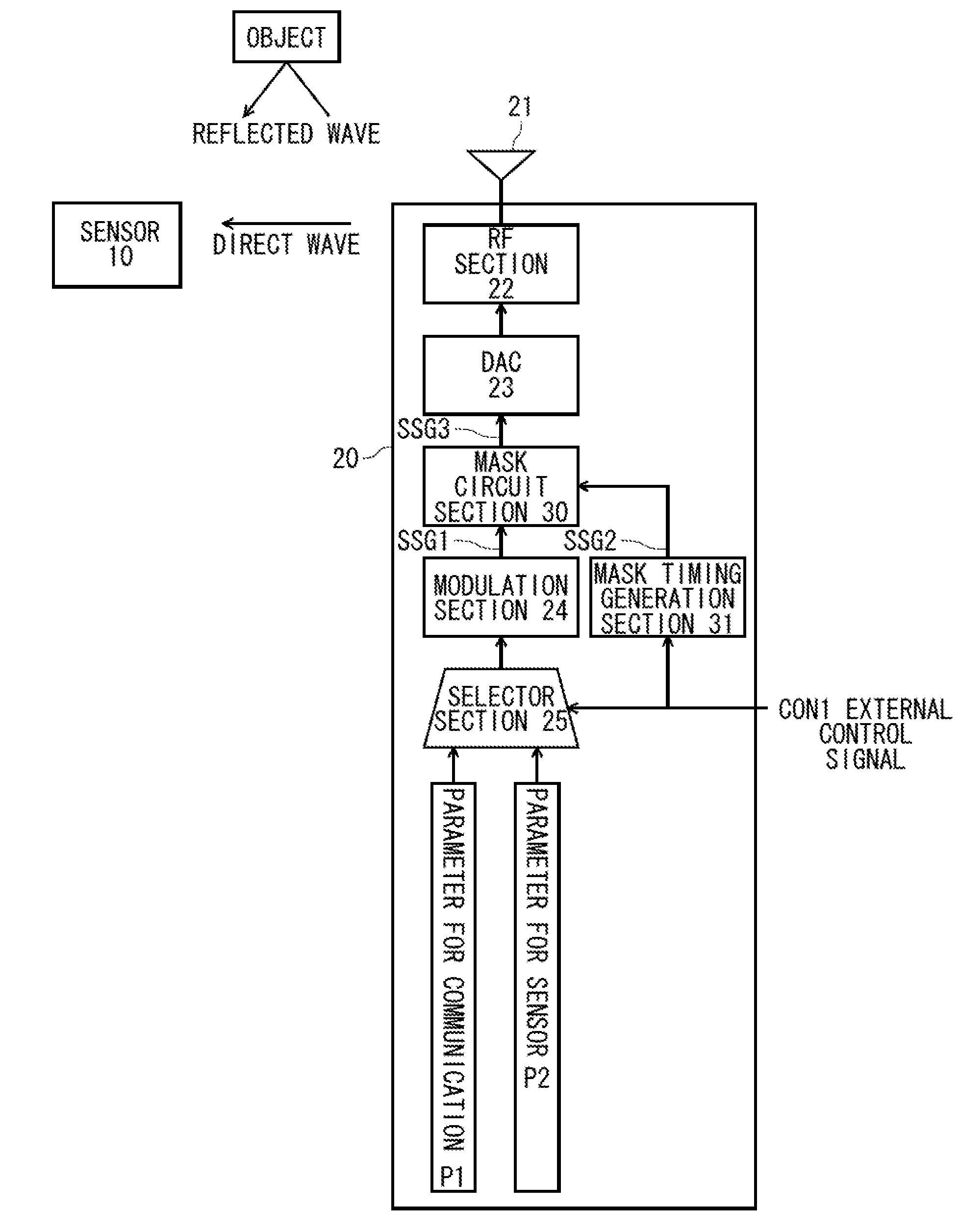
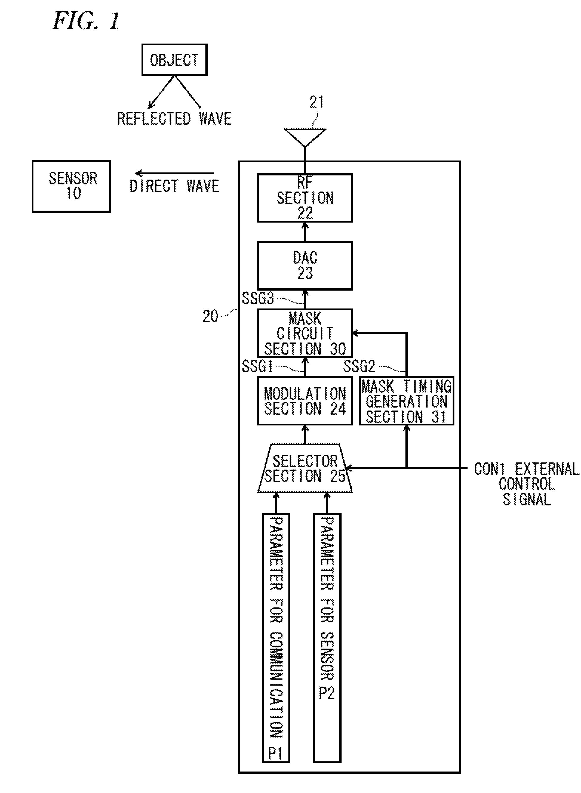
[0060]FIG. 1 is a block diagram illustrating an internal configuration of a WiGig wireless device 20 as a wireless communication device of a first embodiment. The WiGig wireless device 20 operates in accordance with a WiGig specification defined by the Wireless Gigabit Alliance. A frequency band used for wireless communication is a millimeter wave band, for example, 60 GHz band. A wireless communication distance is about 10 m. In addition, FIG. 1 illustrates the main part of the transmission system of the WiGig wireless device 20, and other circuits are omitted.
[0061]The WiGig wireless device 20 illustrated in FIG. 1 has a configuration that includes an antenna 21, an RF section 22, a Digital-Analog Converter (DAC) 23, a modulation section 24, a selector section 25, a mask circuit section 30, and a mask timing generation section 31.
[0062]The modulation section 24 generates a signal frame of the WiGig specification and outputs the generated signal...
second embodiment
[0116](Wireless Communication Device)
[0117]FIG. 5 is a block diagram illustrating an internal configuration of the WiGig wireless device 20BB as a wireless communication device of a second embodiment. The present embodiment is a modification example of the first embodiment. In the WiGig wireless device 20BB illustrated in FIG. 5, the components corresponding to the WiGig wireless device 20 of the first embodiment are denoted by the same reference numerals, and the description thereof will be omitted.
[0118]The WiGig wireless device 20BB illustrated in FIG. 5 has a configuration that includes an antenna 21, a RF section 22, a DAC 23, a modulation section 24B, a selector section 25, a mask circuit section 30, and a mask timing generation section 31. That is, the modulation section 24B is different from the modulation section 24 illustrated in the first embodiment.
[0119]The modulation section 24B has a configuration that includes a Golay signal generation section (referred to as “FGCF” ...
third embodiment
[0155](Wireless Communication Device 2000)
[0156]FIG. 11 is a block diagram illustrating a system configuration of a radiation pattern measurement system 100PPP and an internal configuration of a wireless communication device 2000 in a third embodiment. The frequency band used for wireless communication by the wireless communication device 2000 is a millimeter-wave band, for example, 60 GHz band. A wireless communication distance is about 10 m. Further, in FIG. 11, the main parts of the transmission system of the wireless communication device 2000 are illustrated, and other circuits are not illustrated.
[0157]The wireless communication device 2000 has a beam forming function and has a configuration that includes a plurality of antenna system processing sections (branches) 20A, 20B, 20C, and 20D. Hereinafter, the antenna system processing section is termed as a “branch”. Although the wireless communication device 2000 illustrated in FIG. 11 is configured to include for example, four br...
PUM
 Abstract
Description
Claims
Application Information
 - Generate Ideas
- Intellectual Property
- Life Sciences
- Materials
- Tech Scout
- Unparalleled Data Quality
- Higher Quality Content
- 60% Fewer Hallucinations
Browse by: Latest US Patents, China's latest patents, Technical Efficacy Thesaurus, Application Domain, Technology Topic, Popular Technical Reports.
© 2025 PatSnap. All rights reserved.Legal|Privacy policy|Modern Slavery Act Transparency Statement|Sitemap|About US| Contact US: help@patsnap.com