Oil transporting vaporizer for a smoke generating apparatus to detect leaks in a fluid system

a technology of oil transporting vaporizer and smoke generating apparatus, which is applied in the direction of combustion air/fuel air treatment, lighting and heating apparatus, instruments, etc., can solve the problems of limiting the production of smoke, affecting the quality of smoke production, so as to enhance the contact of oil bubbles and enhance the effect of oil bubbles

Active Publication Date: 2014-03-13
CPS PRODS
View PDF5 Cites 12 Cited by
  • Summary
  • Abstract
  • Description
  • Claims
  • Application Information

AI Technical Summary

Benefits of technology

[0010]To enhance smoke production by the oil transport and vaporizer device, the voltage and current applied to the heater wire are advantageously controlled so as to produce a series of successively rising and falling (i.e., sawtooth) pulses which are optimized to enhance oil bubble contact with the heater wire while limiting peak heater wire temperature. This method of heater wire control advantageously increases the mass transfer rate of the oil transporting vaporizer device, avoids degradation of the oil that is often caused by overheating and improves the quality of the smoke by producing a smoke composed of smaller, more uniform oil mist droplets than can be produced with conventional controls.

Problems solved by technology

However, the woven fiberglass wick used in the conventional smoke producing apparatus described above may ignite and burn at temperatures above 1000° F. or its fiber structures may deteriorate and melt together at temperatures below 1000° F. Consequently, at operating temperatures above 1000° F., this smoke producing apparatus could be damaged and / or the fiberglass wick may require replacement.
Transferring oil from the reservoir to the beater element associated with the stranded fiberglass wick primarily by means of capillary action is a relatively slow process which can delay as well as limit the production of smoke.
This limits the flexibility of a smoke generating apparatus which is unable to adjust its smoke delivery rate as may be required for larger or smaller test systems.

Method used


Image

  • Oil transporting vaporizer for a smoke generating apparatus to detect leaks in a fluid system
  • Oil transporting vaporizer for a smoke generating apparatus to detect leaks in a fluid system
  • Oil transporting vaporizer for a smoke generating apparatus to detect leaks in a fluid system

Examples


Embodiment Construction

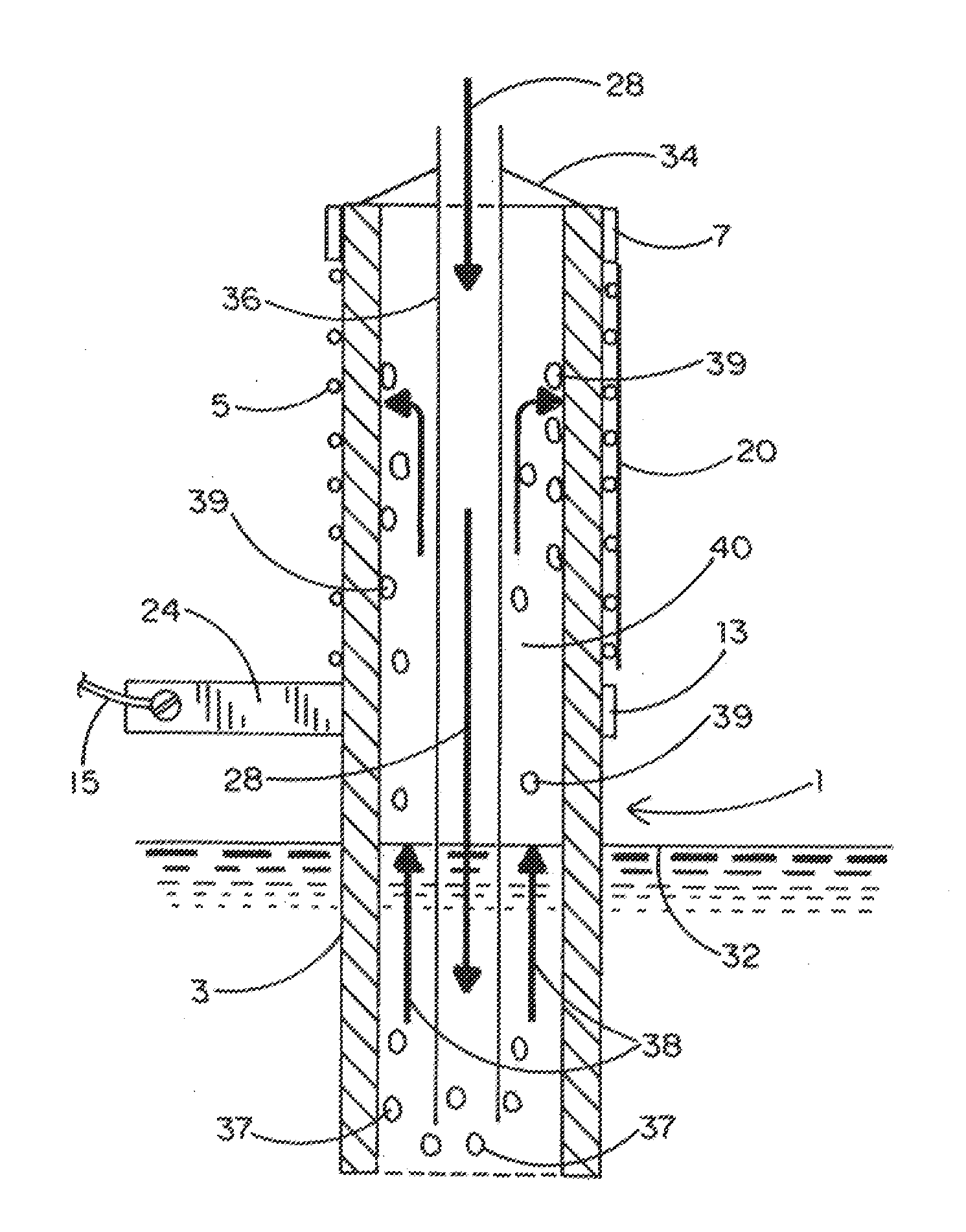
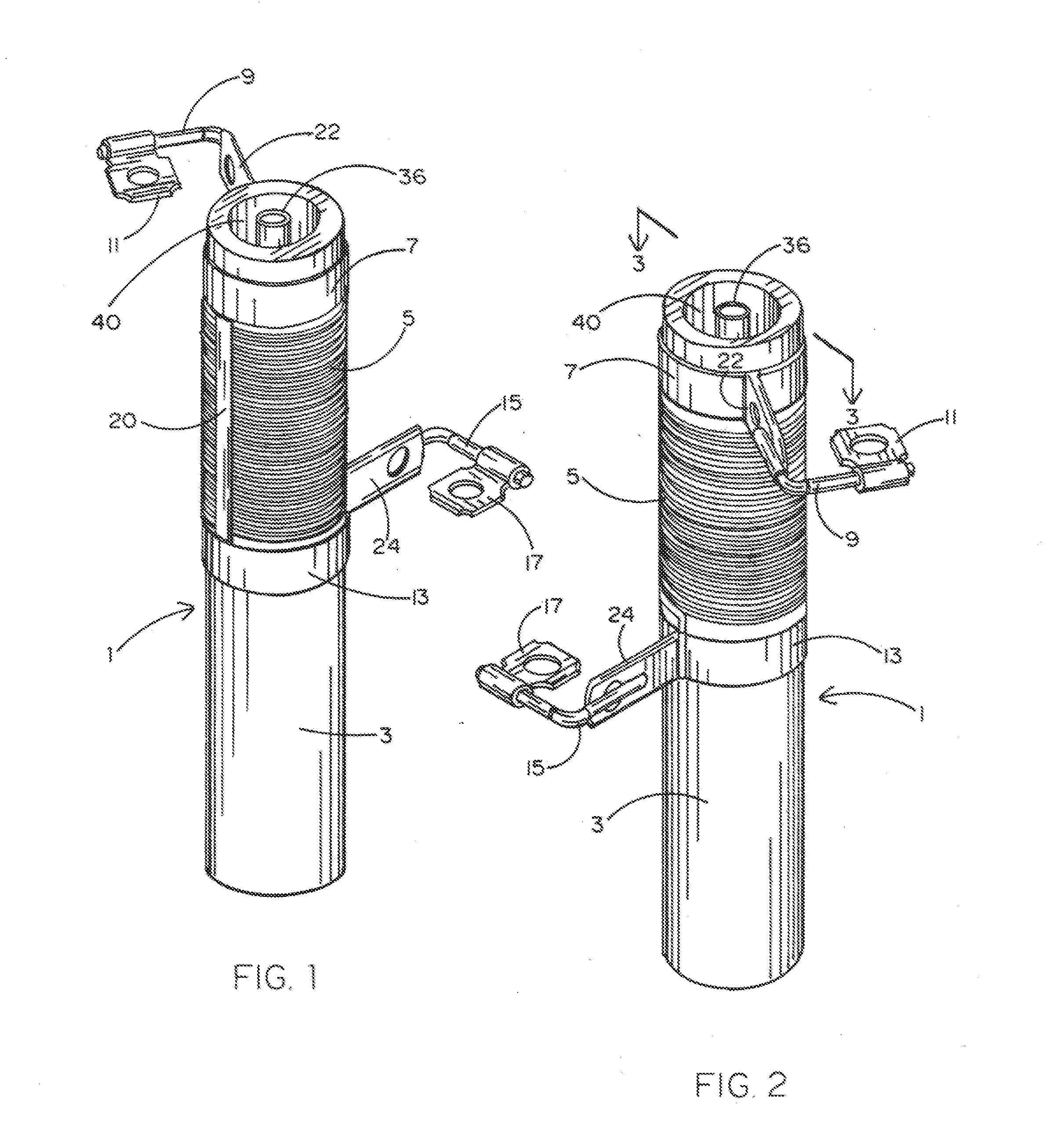
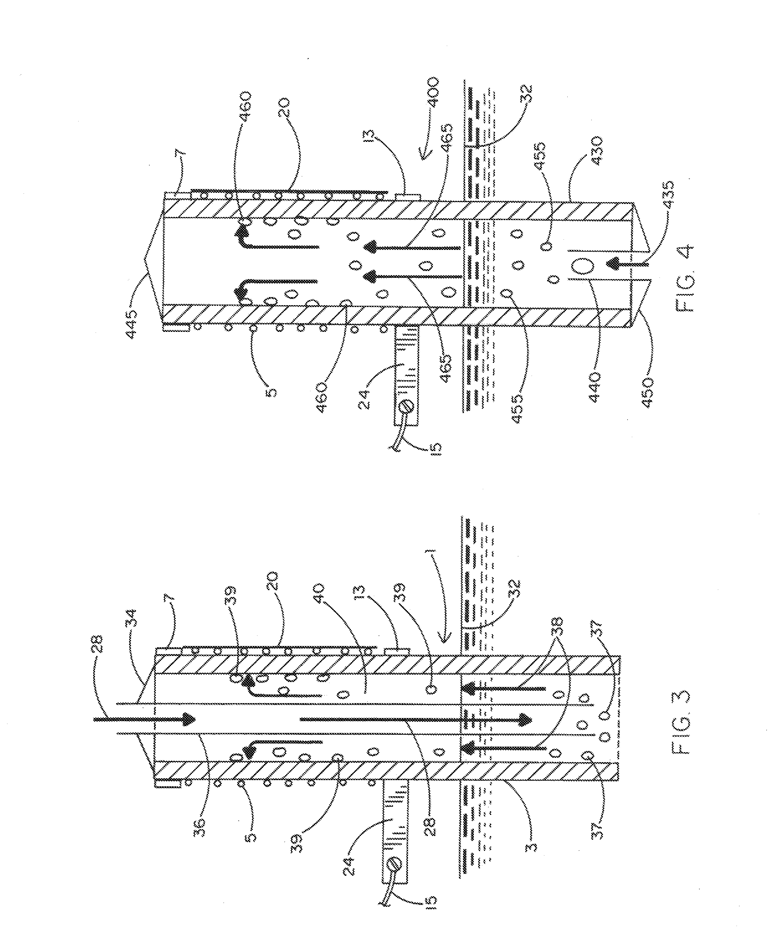
[0025]Described below are improved high temperature oil transport and vaporizer devices for use with conventional apparatus which is adapted to produce a supply of “smoke” for delivery to a fluid, system that is being tested for leaks. The oil transport and vaporizer devices ideally communicate with a closed fluid system, (examples being those common to a motor vehicle such as, but not limited to, the evaporative or air brake system thereof). However, it is to be understood that the smoke generating apparatus may be coupled to other closed fluid systems undergoing testing (e.g., a plumbing system), such that the smoke is delivered to the system in order to detect the presence and location of a leak by visually inspecting the system for any smoke escaping therefrom. As will now be explained, the supply of smoke is efficiently produced by virtue of die oil transporting vaporizers being capable of efficiently transporting a non-toxic petroleum-based oil (e.g., mineral oil), or the like...


PUM


Abstract

An oil transporting vaporizer for a smoke generating apparatus to generate smoke to be supplied to a closed system to be tested for leaks. In a preferred embodiment, the vaporizer includes a hollow tube that is manufactured from a high temperature, fire resistant, porous material (e.g., ceramic). The vaporizer stands in a reservoir of oil such that some of the porous tube is filled with oil from the reservoir. A heater wire surrounds the outside of the porous tube above the oil within the tube. A gas (e.g., air) is blown into the porous tube and towards the oil to cause a mixture of air and gas to move through the tube. Because of its porosity, the air / oil mixture permeates the tube in the vicinity of the heater wire so as to be vaporized into smoke when the heater wire is energized.

Description

BACKGROUND OF THE INVENTION[0001]1. Field of the Invention[0002]This invention relates to an oil transporting vaporizer having particular application for use in a “smoke” generating apparatus and including a hollow tube body that is ideally manufactured from a high temperature, fire-resistant, porous material, such as ceramic, to transport oil from a reservoir thereof to a heater wire that is wound around the tube body. Oil being transported through and over the tube body is vaporized into smoke by the beater wire for delivery to a (e.g., closed fluid) system under test for leaks.[0003]2. Background Art[0004]Smoke generating apparatus are known for generating a visible aerosol mist to be delivered to a fluid system undergoing testing for leaks. While such apparatus are commonly described as smoke machines, it is preferable that the “smoke” be a non-toxic aerosol mist produced by evaporation and condensation at controlled temperatures rather than actual smoke which is a product of pa...

Claims


Application Information

Patent Timeline
Patent Type & Authority Applications(United States)
IPC IPC(8): G01M3/20F22B1/28
CPCF22B1/28G01M3/20
Inventor BANYARD, RICHARD L.MURASHIE, EDWARD A.MCCOLLOM, GREGORY M.
Owner CPS PRODS
Why Eureka
Try Eureka