System and Method for Seed Laser Mode Stabilization

a laser mode and stabilization technology, applied in the direction of laser details, wave amplification devices, electrical equipment, etc., can solve the problems of affecting the stability of the laser mode, the ratio between the duration of the pulse and the time between

Inactive Publication Date: 2014-03-13
ASML NETHERLANDS BV
View PDF3 Cites 16 Cited by
  • Summary
  • Abstract
  • Description
  • Claims
  • Application Information

AI Technical Summary

Benefits of technology

[0018]Another embodiment discloses a method of maximizing the output of a laser that produces output pulses, the laser having an optical cavity with a length and including an optical component at one end that is movable through a predetermined range, such that moving the optical component changes the length of the optical cavity, lasing occurring when power in the optical cavity reaches a lasing threshold, and a variable attenuator in the optical cavity for limiting a rate at which power increases in the laser and thus controlling a time at which the lasing threshold is reached and a time at which an output pulse is released, the method comprising: operating the laser by a computing device while moving the optical component through the predetermined range of motion; measuring with a sensor an output energy of the laser at a plurality of times during the moving of the optical component; calculating by the computing device a time delay from the release of an output puke to the lasing threshold next being reached; selecting by the computing device a position of the optical component at which the time delay is at a minimum; moving the optical component to the selected position by an actuator based upon the selected position; and adjusting the variable attenuator by a controller based upon the measured time delay to keep the time delay at a desired value.

Problems solved by technology

However, even with the use of a seed laser, it is still desirable to generate a sufficiently large laser pulse so that the need for amplification can be limited.
Such a solution would be extremely wasteful, as the typical duty cycle, i.e., the ratio between the duration of the pulse to the time between pulses, is very low, typically on the order of 1%.
Thus, 99% of the output power of the laser would be wasted.
However, Q-switching with an infrared laser, such as a CO2 laser, suffers from another problem.
When the Q-switch is opened, allowing lasing to occur, there is a statistical uncertainty as to when the first photons will be emitted within the cavity, so that the precise timing of when the pulse will be generated is not predictable.
Pre-lasing also suffers from temporal jitter, but as long as pre-lasing occurs, a larger pulse will occur when the shutter is opened.
Pre-lasing suffers from a different timing problem, however.
There is also another problem that is separate from, and not solved by, Q-switching or pre-lasing.
If the relationship of those frequencies to the laser's gain changes due to a change in the cavity length, for example due to thermal effects, the available power of the laser can decrease significantly.

Method used


Image

  • System and Method for Seed Laser Mode Stabilization
  • System and Method for Seed Laser Mode Stabilization
  • System and Method for Seed Laser Mode Stabilization

Examples


Embodiment Construction

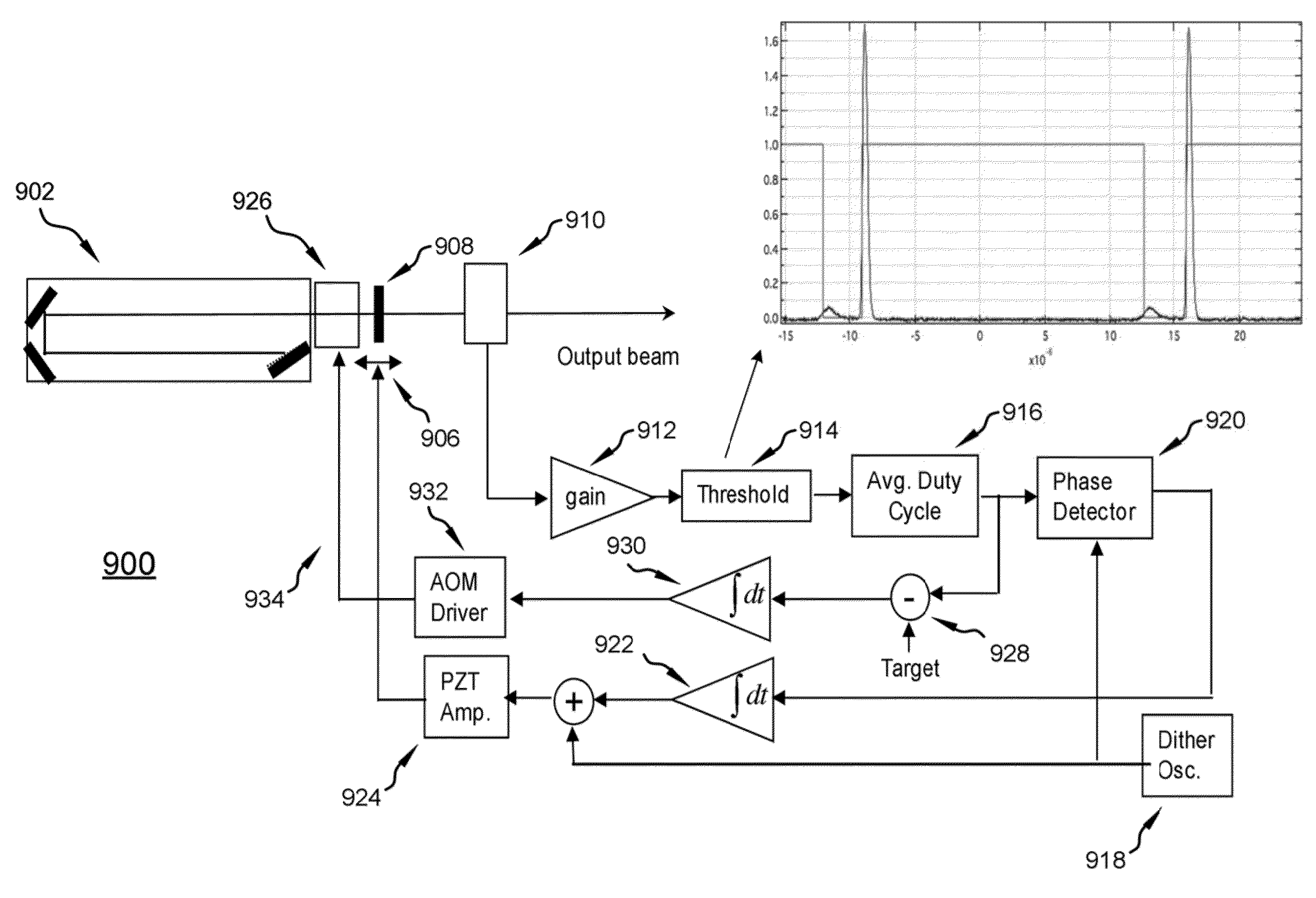
[0030]The present application describes a method and apparatus for stabilizing a seed laser source(s) such as might be used in a laser produced plasma (LPP) extreme ultraviolet (EUV) light system.

[0031]In one embodiment, a method of stabilizing a seed laser source involves adjusting the cavity length of the laser by ill cans of a movable mirror forming one end of the cavity. The average output energy of the laser is measured at different mirror positions, and a mirror position selected which results in a cavity mode being aligned with the gain peak of the laser, thus producing a minimum pre-lasing delay from the termination of the previous pulse to the resumption of pre-lasing for the next output pulse, and thus jitter-free timing of output pulses. Feedback loops keep the laser output at maximum gain and efficiency, and the attenuation and timing at a desired operating point.

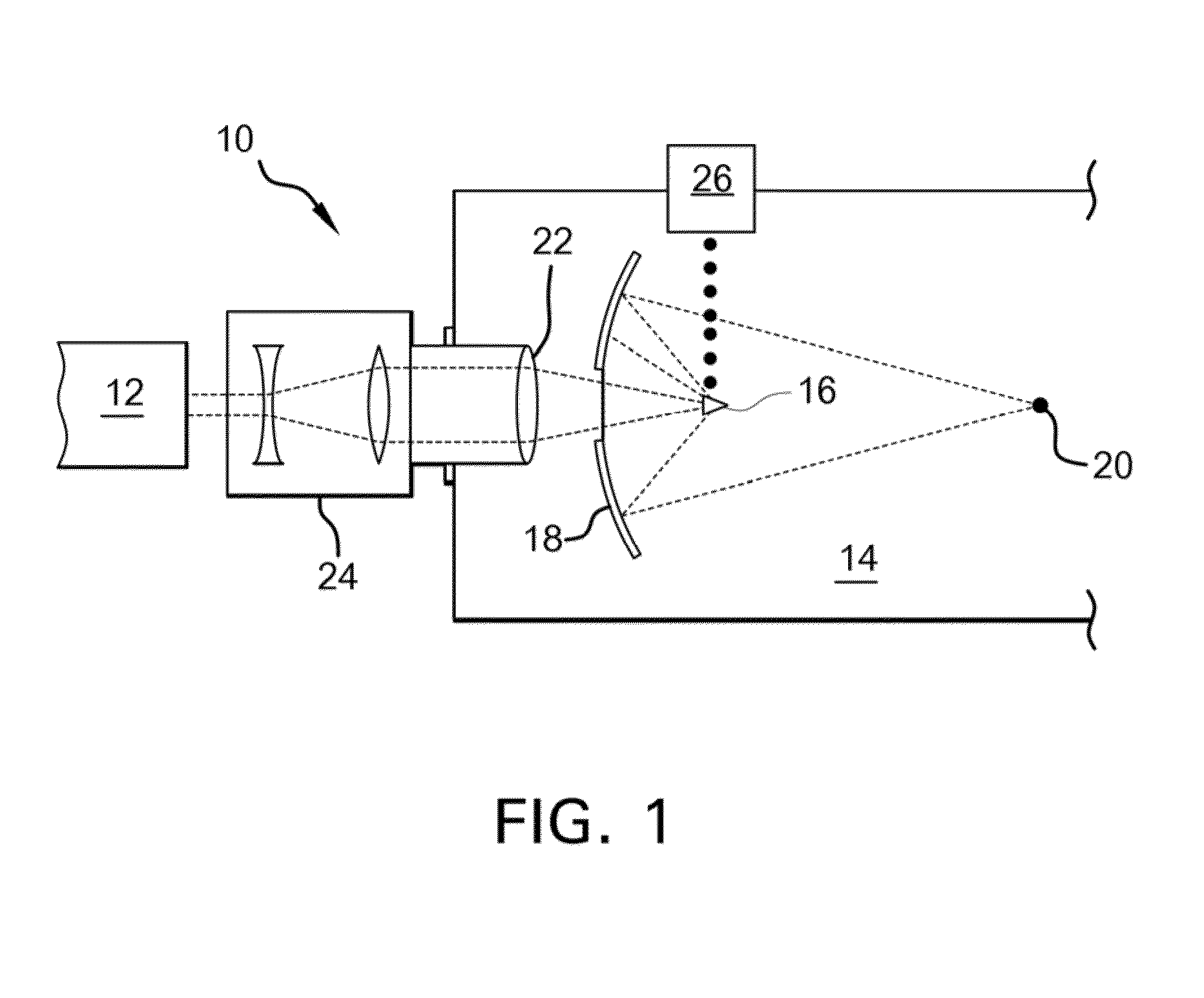
[0032]FIG. 1 is a simplified schematic view of some of the components of one embodiment of an LPP EUV light s...


PUM


Abstract

A method and apparatus for stabilizing the seed laser in a laser produced plasma (LPP) extreme ultraviolet (EUV) light system are disclosed. In one embodiment, the cavity length of the laser may be adjusted by means of a movable mirror forming one end of the cavity. The time delay from the release of an output pulse to the lasing threshold next being reached is measured at different mirror positions, and a mirror position selected which results in a cavity mode being aligned with the gain peak of the laser, thus producing a minimum time delay from an output pulse of the laser to the next lasing threshold. A Q-switch in the laser allows for pre-lasing and thus jitter-free timing of output pulses. Feedback loops keep the laser output at maximum gain and efficiency, and the attenuation and timing at a desired operating point.

Description

FIELD OF THE INVENTION[0001]The present invention relates generally to laser produced plasma extreme ultraviolet light sources. More specifically, the invention relates to a method and apparatus for the use of seed lasers as such light sources.BACKGROUND OF THE INVENTION[0002]The semiconductor industry continues to develop lithographic technologies which are able to print ever-smaller integrated circuit dimensions. Extreme ultraviolet (“EUV”) light (also sometimes referred to as soft x-rays) is generally defined to be electromagnetic radiation having wavelengths of between 10 and 120 nanometers (nm). EUV lithography is currently generally considered to include EUV light at wavelengths in the range of 10-14 nm, and is used to produce extremely small features, for example, sub-32 nm features, in substrates such as silicon wafers. To be commercially useful, it is desirable that these systems be highly reliable and provide cost effective throughput and reasonable process latitude.[0003]...

Claims


Application Information

Patent Timeline
Patent Type & Authority Applications(United States)
IPC IPC(8): H01S3/13
CPCH01S3/13H01S3/1305H01S3/136H01S3/1398H01S3/2366H01S3/2383H01S3/0085H05G2/005H05G2/008H01S3/0064H01S3/117H01S3/11
Inventor SANDSTROM, RICHARD L.
Owner ASML NETHERLANDS BV
Why Eureka
Try Eureka