Methods of forming blades and method for rendering a blade resistant to erosion

a technology of turbine blades and blade chords, which is applied in the direction of turbines, manufacturing tools, machines/engines, etc., can solve the problems of substantial erosion of rear-stage turbine blades, loss of blade chord width, and component prone to erosion

Active Publication Date: 2014-03-13
GENERAL ELECTRIC CO
View PDF2 Cites 29 Cited by
  • Summary
  • Abstract
  • Description
  • Claims
  • Application Information

AI Technical Summary

Benefits of technology

[0008]According to another exemplary embodiment of the present disclosure, a method for rendering a blade resistant to erosion is provided. The method includes positioning a backing plate adjacent to at least one side of a forward face of a leading edge surface of the blade. The method includes bonding an erosion resistant material to the forward face of the leading edge surface of the blade, wherein the erosion resistant material forms an erosion shield and a leading edge of the blade. The method includes heat treating the blade and the erosion shield and removing the backing plate wherein the erosion shield is substantially free of any diffusion layer induced by the backing plate.

Problems solved by technology

Components in power generation systems, such as the turbine rotor blades and the turbine stator blades that are used in turbine equipment are exposed to an erosive environment in which these components are susceptible to erosion caused by water droplets in the steam and by fine dust from oxide scale.
In particular, water droplets can cause substantial erosion of rear-stage turbine blades, where such water droplets are mixed into the steam for turbine driving.
Erosion of turbine blades is problematic because it results in loss of blade chord width, loss of turbine efficiency, and fatigue breakdown of the blade brought about by erosion.
These residual stresses, which are difficult to remedy significantly through heat treatment after build-up welding, may give rise to spalling in the form of peeling of the end of the build-up portion, or cracking at the weld metal portions, in the environment where the turbine operates.

Method used


Image

  • Methods of forming blades and method for rendering a blade resistant to erosion
  • Methods of forming blades and method for rendering a blade resistant to erosion
  • Methods of forming blades and method for rendering a blade resistant to erosion

Examples


Embodiment Construction

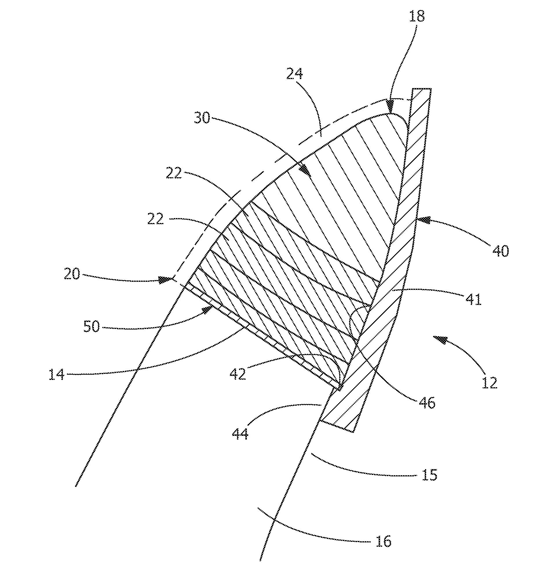
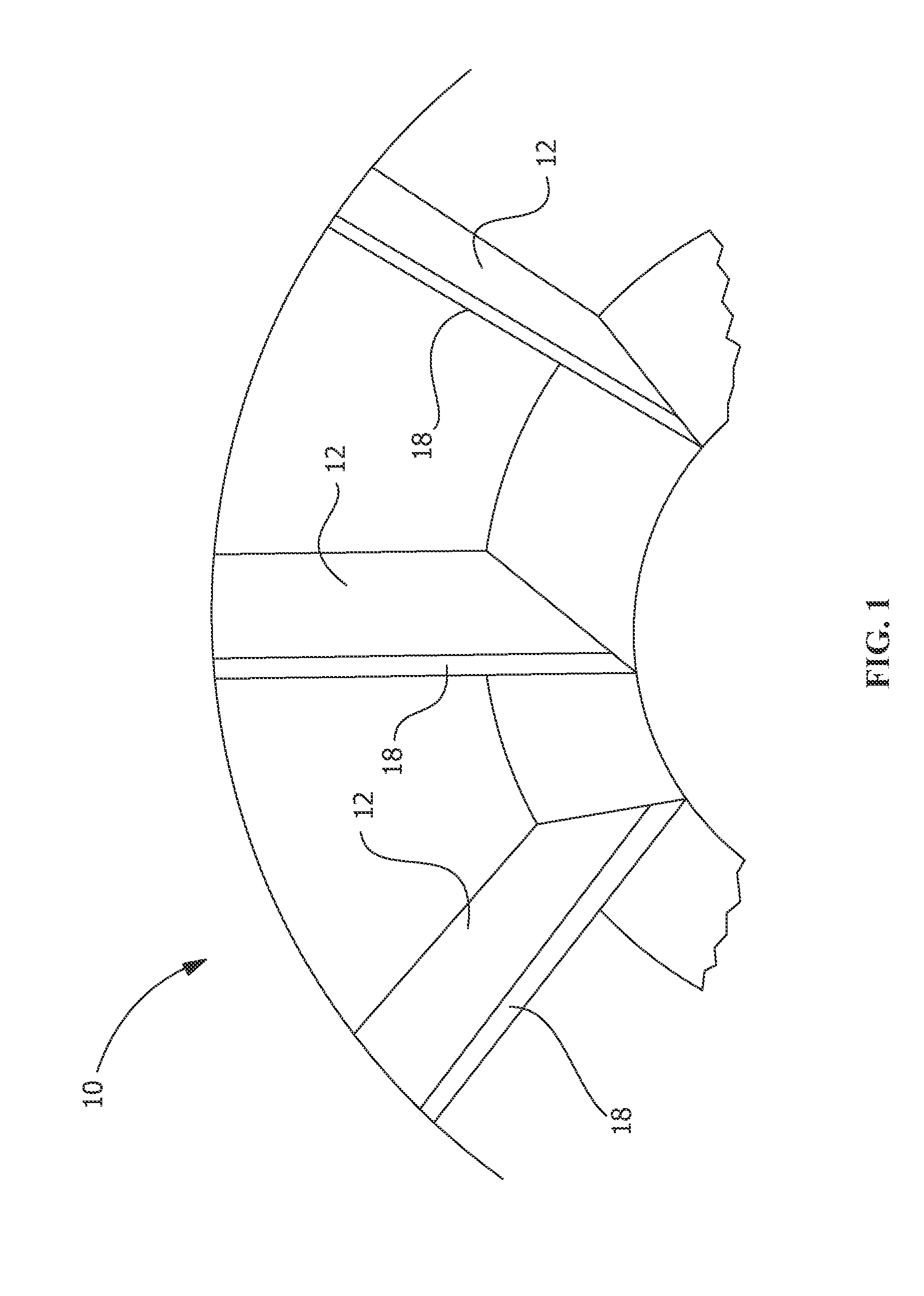
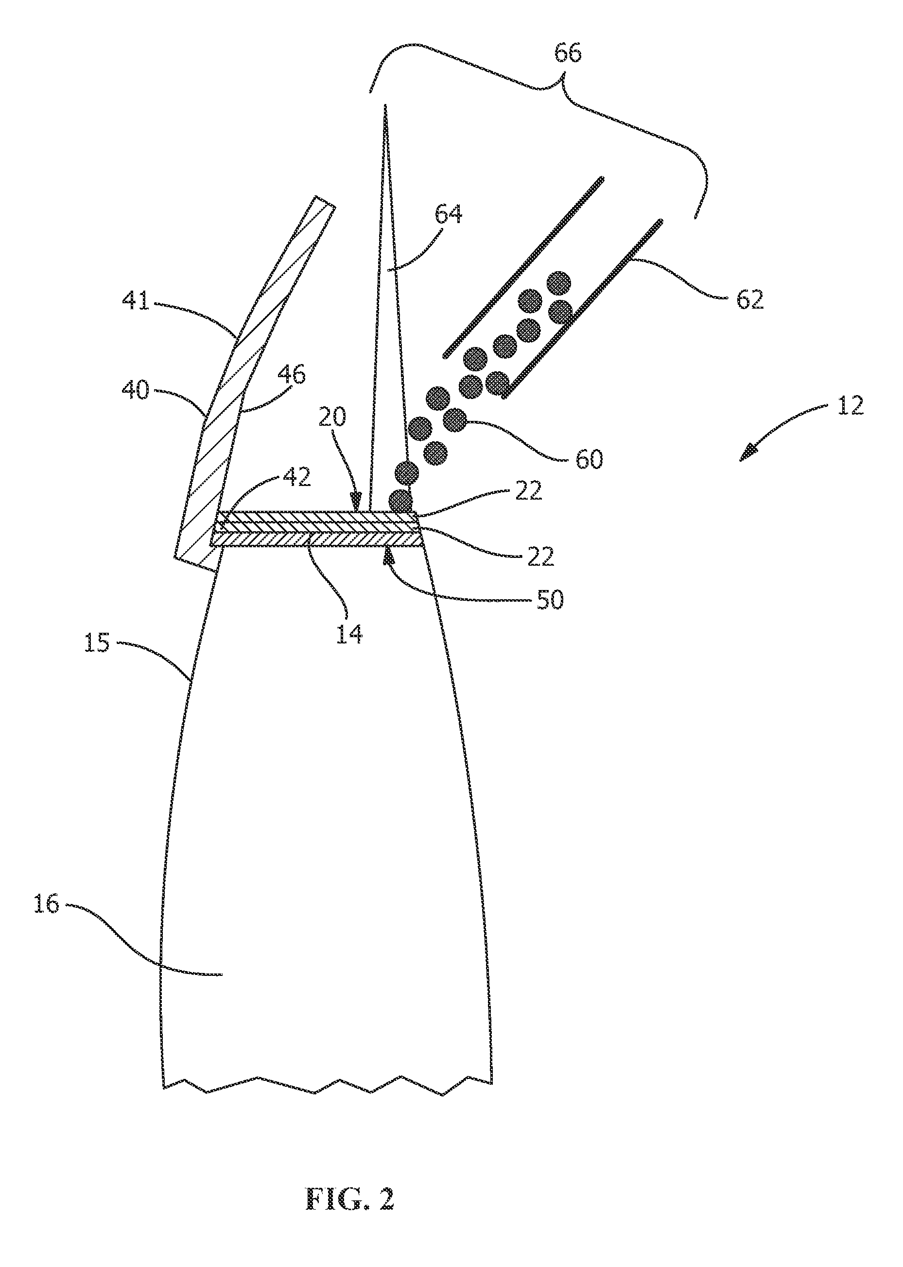
[0017]Provided are methods of forming a blade for a turbine and a method for rendering a turbine blade resistant to erosion that do not suffer from the drawbacks in the prior art. One advantage of an embodiment of the present disclosure is that the method allows for stronger and less stressed joining of two dissimilar metals. Another advantage is the backing plates of the present disclosure provide support for laser cladding buildup on the leading edge of the blade. Yet another advantage is that the cladding of the erosion resistant material is built up from the backing plate and the cutoff edge of the blade simultaneously. Another advantage is a larger melt pool can be produced using the backing plate of the present disclosure, which allows for more cladding powder to be deposited into the melt pool. Yet another advantage of an embodiment of the present disclosure is that the method allows for greater cladding application speeds and reduced cycle time because of the larger melt poo...


PUM

PropertyMeasurementUnit
thicknessaaaaaaaaaa
thicknessaaaaaaaaaa
thicknessaaaaaaaaaa

Abstract

Methods of forming a blade and rendering a blade resistant to erosion includes positioning a backing plate(s) or elongated backing plate(s) adjacent at least one side of a forward face of a leading edge surface of the blade. The methods include depositing an erosion resistant material in a plurality of layers by fusion bonding the erosion resistant material to the forward face of the leading edge surface of the blade. The backing plates providing a template or guide for depositing the plurality of layers of erosion resistant material. The plurality of layers of erosion resistant material form an erosion shield and a leading edge of the blade. Methods include removing the backing plate.

Description

FIELD OF THE INVENTION[0001]The present invention relates generally to power generation systems and more specifically to a method of forming a blade for a turbine and a method for rendering a turbine blade resistant to erosion.BACKGROUND OF THE INVENTION[0002]Components in power generation systems, such as the turbine rotor blades and the turbine stator blades that are used in turbine equipment are exposed to an erosive environment in which these components are susceptible to erosion caused by water droplets in the steam and by fine dust from oxide scale. In particular, water droplets can cause substantial erosion of rear-stage turbine blades, where such water droplets are mixed into the steam for turbine driving. Erosion of turbine blades is problematic because it results in loss of blade chord width, loss of turbine efficiency, and fatigue breakdown of the blade brought about by erosion.[0003]Various erosion preventive measures have been implemented to try to increase the durabili...

Claims


Application Information

Patent Timeline
Patent Type & Authority Applications(United States)
IPC IPC(8): B05D3/12B23K31/02B05D1/36
CPCB23K26/342B23K26/702B23K2101/001F01D5/286F01D5/288F05D2220/31
Inventor JONES, MICHAEL LEWISGANESH, SWAMI
Owner GENERAL ELECTRIC CO
Why Eureka
Try Eureka