

Generating deoxygenated pyrolysis vapors
a pyrolysis vapor and oxygenated technology, applied in the direction of biofuels, waste based fuels, combustible gas catalytic treatment, etc., can solve the problems of high oxygenated pyrolysis oil (or pyoil) that is not practical for upgrading, catalysts tend to rapidly deactivate, and liquid product containing solids and metals that can negatively impact downstream processes. , to achieve the effect of prolonging the activity of upgrading catalys
Inactive Publication Date: 2014-03-13
PHILLIPS 66 CO
View PDF5 Cites 1 Cited by
- Summary
- Abstract
- Description
- Claims
- Application Information
AI Technical Summary
Benefits of technology
The patent describes a process for upgrading a gas / liquid mixture using a catalyst. The process aims to reduce the amount of metal in the gas / liquid mixture and prevent char from leaving the reactor. This increases the activity of the catalyst and reduces the time needed for the gas / liquid mixture to produce secondary products. The technical effects of this process are improved efficiency and selectivity for upgrading gas / liquid mixtures.
Problems solved by technology
The products also include a highly oxygenated pyrolysis oil (or pyoil) that is not practical for upgrading to a transportation fuel because of thermal stability issues associated with highly reactive oxygenated components.
Unfortunately, when employing this process, the catalysts tend to rapidly deactivate when contacted by char fines composed of carbon and metals.
Additionally, the char fines are often carried out of the pyrolyzer by entrainment with the pyrolysis vapor, resulting in a liquid product containing solids and metals that can negatively impact downstream processes.
Method used
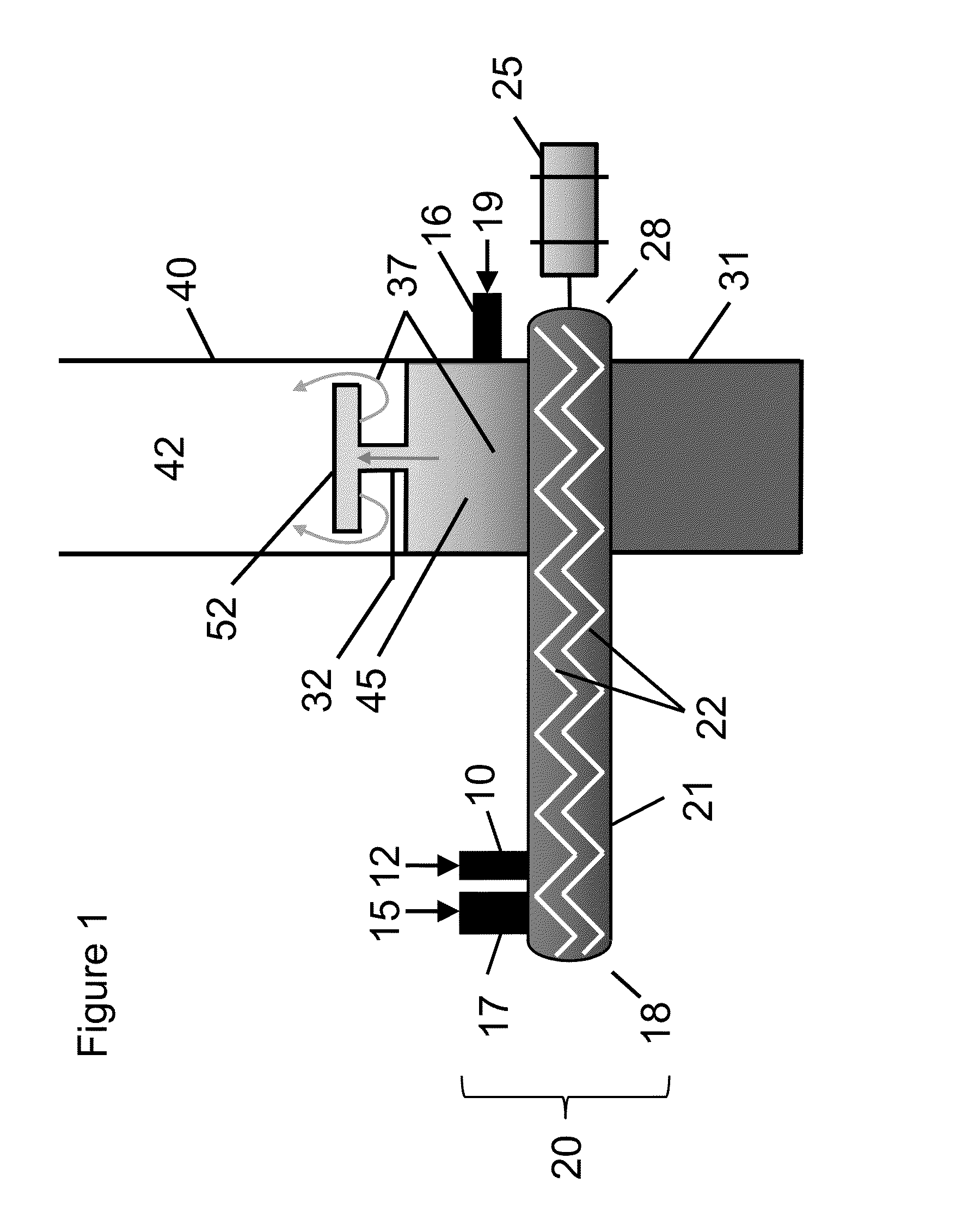
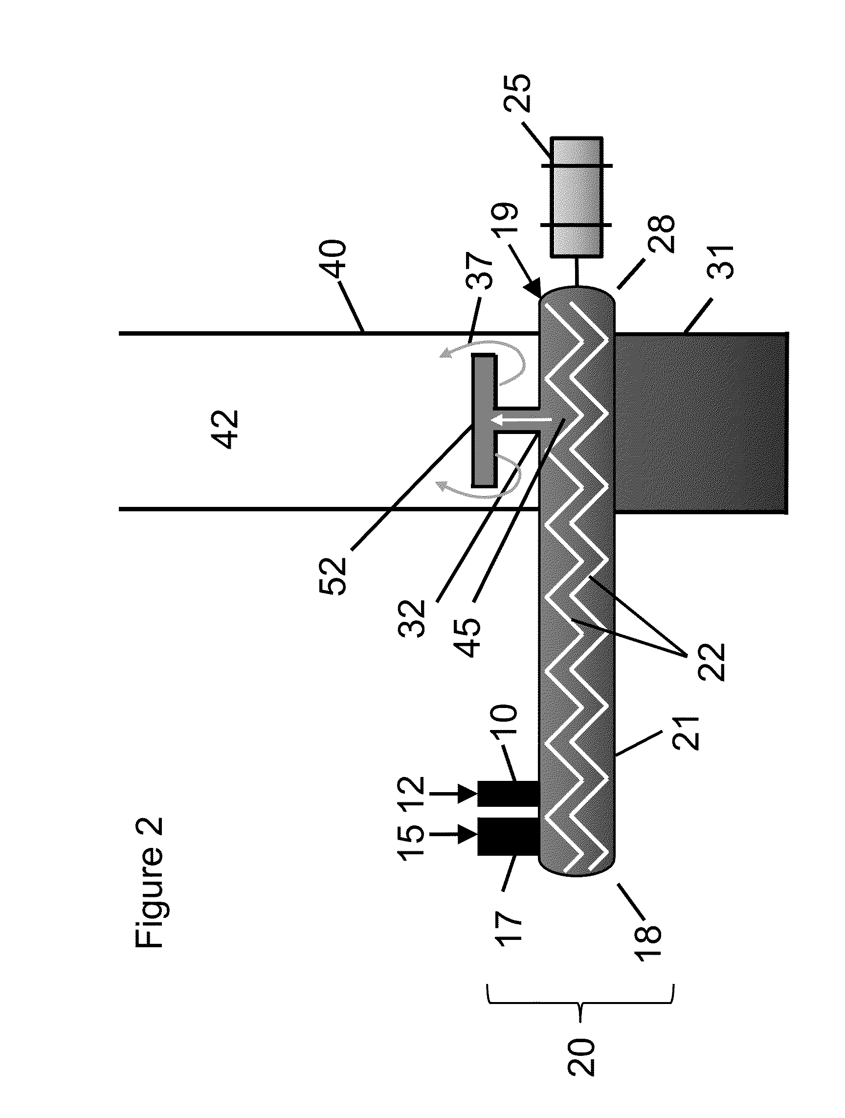
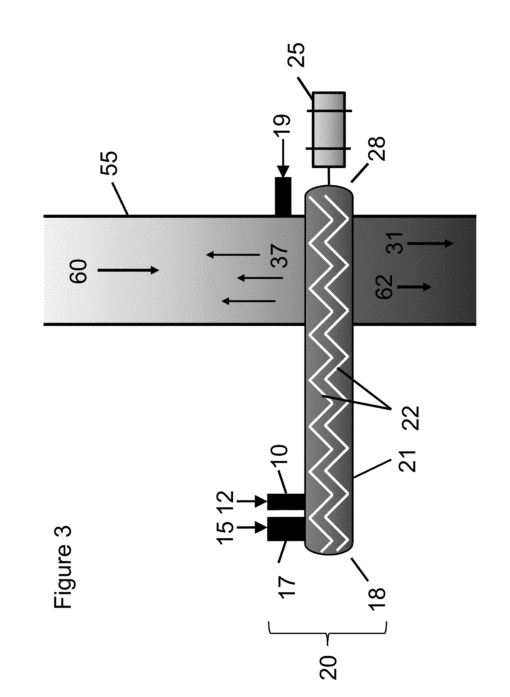
View moreImage
Smart ImageViewing Examples

Examples
example 1
[0047]FIG. 4 demonstrates that at 3 seconds of vapor residence time in a 100 micron capillary maintained at pyrolysis temperatures (610° F.), the proportion of C16+ species increased relative to levoglucosan, a key six carbon primary pyrolysis product. Furthermore, the proportion of phenolics, furans, and other carbohydrates / sugars comprising less than 16 carbon atoms decreased at the longer residence times, likely from oligomerization of these primary compounds to heavier compounds of 16 carbons, or greater, which are difficult to upgrade to fuel range hydrocarbons.
Login to View More PUM
 Abstract
Description
CROSS-REFERENCE TO RELATED APPLICATIONS[0001]This application is a non-provisional application which claims benefit under 35 USC §119(e) to U.S. Provisional Application Ser. No. 61 / 699,000 filed Sep. 10, 2012, entitled “Generating Deoxygenated Pyrolysis Vapors,” which is incorporated herein in its entirety.STATEMENT REGARDING FEDERALLY SPONSORED RESEARCH OR DEVELOPMENT[0002]None.FIELD OF THE INVENTION[0003]This invention relates to pyrolysis of organic matter into useful chemical or fuel products.BACKGROUND[0004]The U.S. Renewable Fuel Standards (RFS) mandate will require higher volumes of advanced biofuels to be produced in the near future. One method being developed to meet this mandate is the fast pyrolysis of biomass. Conventional biomass fast pyrolysis requires rapid heating of biomass in the absence of oxygen. Products include a solid carbonaceous char that contains the vast quantities of metals (e.g. Na, K, Mg) present in the biomass feedstock. The products also include a hig...
Claims
Login to View More Application Information
Patent Timeline
 IPC IPC(8): C10G1/00
CPCC10G1/002C10K1/30C10K3/02C10B49/16C10B53/02C10G2300/1011C10G2/32C10G3/55C10G3/42Y02P20/145Y02P30/20C10G1/02Y02E50/30Y02E50/10C10J3/52
Inventor HUGHES, MARK A.GORKE, JOHNATHAN T.JONES, SAMUEL T.SHI, TIE-PANREBACZ, NATALIE A.LOTERO, EDGAR
Owner PHILLIPS 66 CO