Heat exchanger arrangement for heat uptake and air conditioning system of a motor vehicle

a technology of heat exchanger and air conditioner system, which is applied in the direction of domestic cooling apparatus, lighting and heating apparatus, and circulation of cooling fluid, etc., can solve the problems of time-consuming and cost-intensive repair, high installation cost, and inability so as to reduce the power needed to heat up the passenger compartment

Active Publication Date: 2014-03-20
HANON SYST
View PDF3 Cites 35 Cited by
  • Summary
  • Abstract
  • Description
  • Claims
  • Application Information

AI Technical Summary

Benefits of technology

[0038]The solution of the invention has various benefits: efficient air conditioning system for simultaneous dehumidification and heating; quick providing of warm air at low outdoor temperatures and cold engine cooling water in the case of motor vehicles with internal combustion engine; reduction of the power needed to heat up the passenger compartment by circulating air operation and/or by specific air guidance within the flow channels; efficient heating operation by warming of the refrigerant at the suction pressure side above the outdoor temperature, the evaporator being supplied with circulating air or partial circulating air, so that the air temperature upstream f

Problems solved by technology

Due to the many components, various installation steps are necessary, which in turn involve a large number of connections and make the installation a costly process.
The connections to be made during the installation process are furthermore potential leakage sites, which may be very time consuming and cost-intensive to repair.
Furthermore, the filling of the air conditioning system with refrigerant occurs only after the installation of all components belonging to the refrigerant circuit.
This further increases the installation expense during the vehicle assembly process.
Air conditioning systems of this kind with coolant/air heat exchangers, which draw their heating power from the coolant circuit of an efficient internal combustion engine of the vehicle drive train, can no longer achieve the temperature level needed for a comfortable heating of the passenger compartment at low outside temperatures, such as below −10° C. The same holds for systems in vehicles with hybrid drive system.
Consequently, the internal combustion engine will be operated for a longe

Method used


Image

  • Heat exchanger arrangement for heat uptake and air conditioning system of a motor vehicle
  • Heat exchanger arrangement for heat uptake and air conditioning system of a motor vehicle
  • Heat exchanger arrangement for heat uptake and air conditioning system of a motor vehicle

Examples


Embodiment Construction

[0058]The following detailed description and appended drawings describe and illustrate various exemplary embodiments of the invention. The description and drawings serve to enable one skilled in the art to make and use the invention, and are not intended to limit the scope of the invention in any manner.

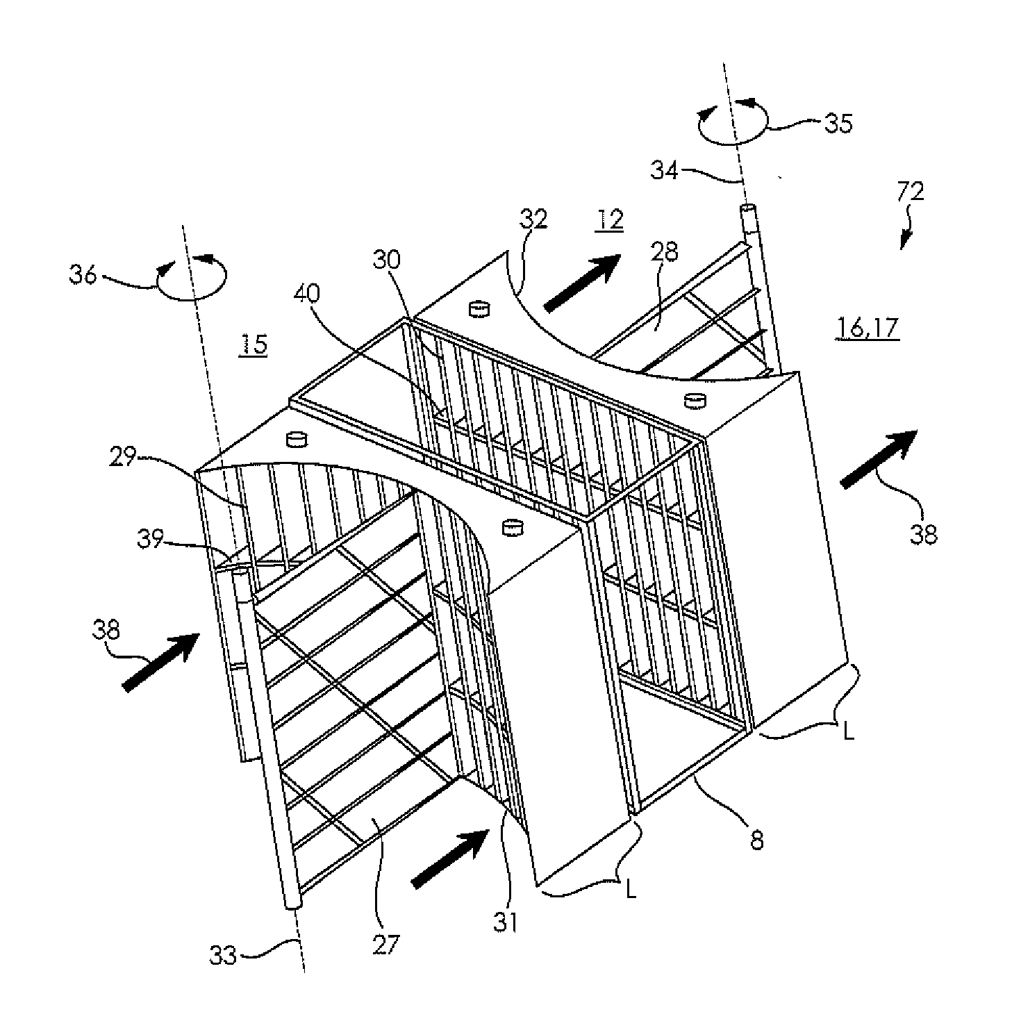
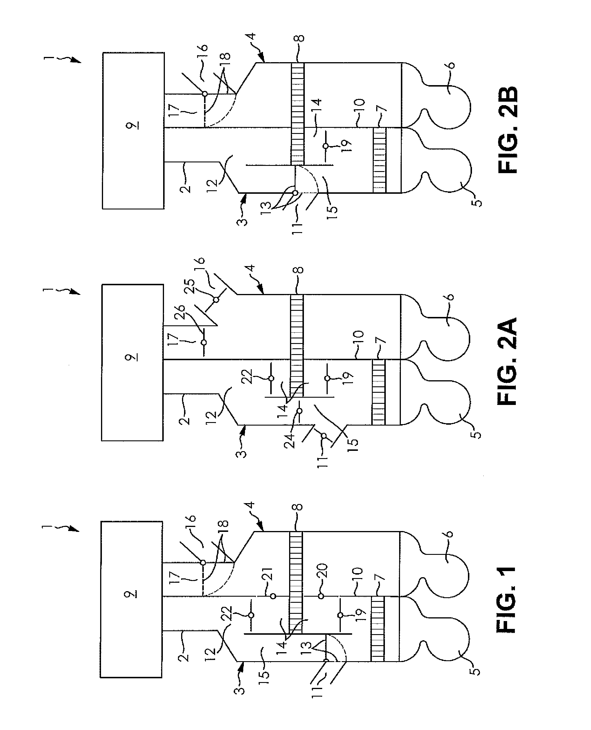
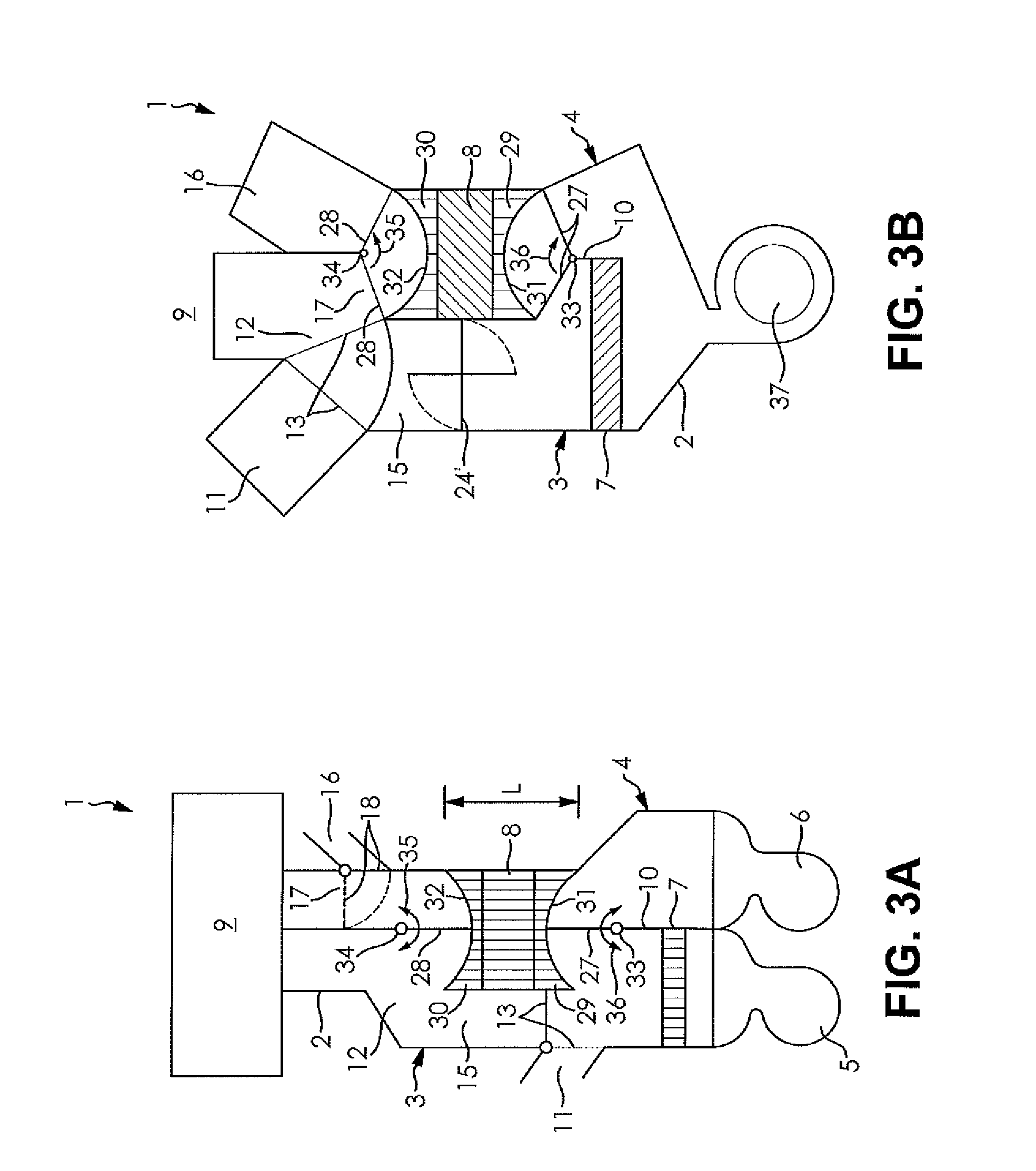
[0059]FIG. 1 shows an air conditioning system 1 with a housing 2, having a first flow channel 3 as well as a second flow channel 4, wherein each flow channel 3, 4 is associated with a fan 5, 6 and can be supplied with fresh air from the outside, circulating air from a passenger compartment 9, or a mixture of both.

[0060]In the first flow channel 3 is arranged an evaporator 7 and in the second flow channel 4 a condenser 8, both of these being configured as components of a refrigerant circuit of the air conditioning system 1 and as air-fed heat exchangers. The evaporator 7 occupies the entire flow cross section of the flow channel 3. The condenser 8 spans the flow channels 3, 4 and has ...


PUM


Abstract

The invention concerns an air conditioning system for conditioning the air of a passenger compartment of a motor vehicle including a housing with a first flow channel and a second flow channel for conducting air and a refrigerant circuit with an evaporator and a condenser. The evaporator is arranged in the first flow channel and the condenser in the second flow channel. The air conditioning system is designed for cooling and heating the passenger compartment and for a reheat operation. The setting of the operating mode is done only via the controlling of air guidance mechanisms. One of the heat exchangers evaporator or condenser is arranged with a part of the heat transfer surface in both the first and the second flow channel.

Description

CROSS-REFERENCE TO RELATED APPLICATION[0001]This application claims priority to German Non-Provisional Patent Application Serial No. DE 10 2012 108 891.8 filed Sep. 20, 2012, hereby incorporated herein by reference in its entirety.FIELD OF THE INVENTION[0002]The invention concerns an air conditioning system for conditioning the air of a passenger compartment of a motor vehicle. The air conditioning system has a housing with a first and a second flow channel for conducting the air, as well as a refrigerant circuit with an evaporator, a compressor, a condenser and an expansion element, wherein the evaporator is arranged in the first flow channel and the condenser in the second flow channel. Furthermore, the invention concerns an air guidance device for a heat exchanger and a method for operating the air conditioning system for a combined refrigeration and heating mode, as well as for a reheating mode for conditioning the air of the passenger compartment. The air guidance device has st...

Claims


Application Information

Patent Timeline
IPC IPC(8): B60H1/32
CPCB60H1/3202B60H1/00071B60H1/00564B60H1/3204B60H3/024B60H1/00028B60H1/00057B60H2001/00085B60H2001/00092B60H2001/00178
Inventor KLEIN, TORSTENDELLA ROVERE, ROBERTOGRAAF, MARCRICHTER, GERALDGIRMSCHEID, FELIX
Owner HANON SYST
Why Eureka
Try Eureka