Thermal flow sensor with vibrating element and gas sensor comprising at least one such sensor

a technology of gas sensor and vibrating element, which is applied in the direction of instrument, liquid/fluent solid measurement, volume/mass flow by dynamic fluid flow effect, etc., can solve the problems of increasing the complexity and cost of such an apparatus, the sensor only allows the detection of organic components, and the size of the sensor cannot be reduced. , to achieve the effect of high sensitivity

Active Publication Date: 2014-03-20
COMMISSARIAT A LENERGIE ATOMIQUE ET AUX ENERGIES ALTERNATIVES
View PDF0 Cites 22 Cited by
  • Summary
  • Abstract
  • Description
  • Claims
  • Application Information

AI Technical Summary

Benefits of technology

[0013]It is consequently one aim of the present invention to offer a thermal flow sensor that offers high sensitivity and can be miniaturized.

Problems solved by technology

On the one hand, the sensor only allows the detection of organic components.
Lastly, the size of the sensor cannot be reduced.
However, to be able to detect other types of gases, the number of laser sources would need to be multiplied, which would considerably increase the complexity and cost of such an apparatus.
The sensors are also difficult to miniaturize.
Micrometric or nanometric sensors suffer from drift problems, i.e., random long-term drifts in the property to be measured and extreme sensitivity to the initial surface states.
This represents a significant limitation of the detector.
Furthermore, a major contrast of thermal constants exists between these light gases and the analytes to be detected, which makes the system more sensitive than under a simple flow of dry air.

Method used


Image

  • Thermal flow sensor with vibrating element and gas sensor comprising at least one such sensor
  • Thermal flow sensor with vibrating element and gas sensor comprising at least one such sensor
  • Thermal flow sensor with vibrating element and gas sensor comprising at least one such sensor

Examples


first embodiment

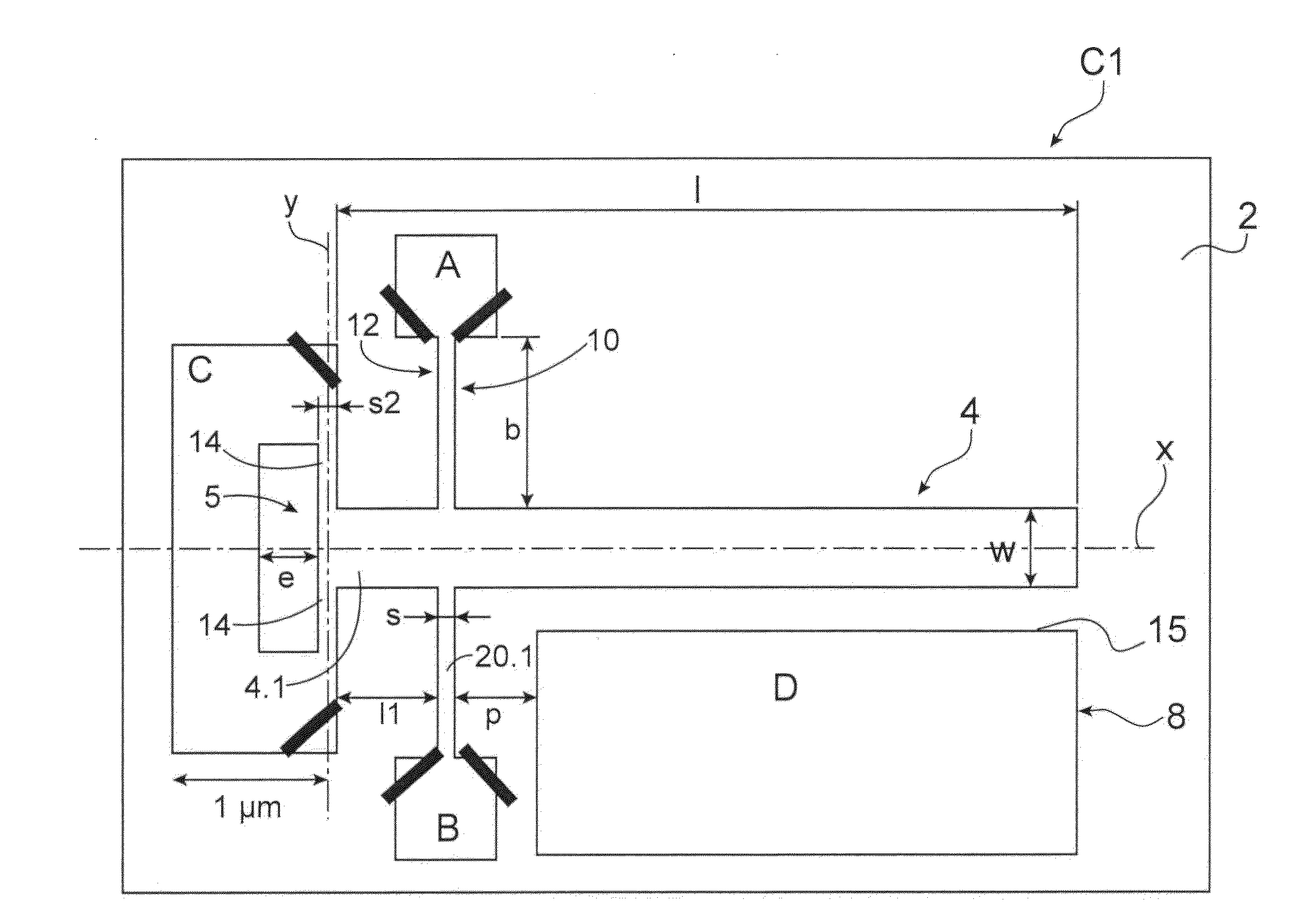
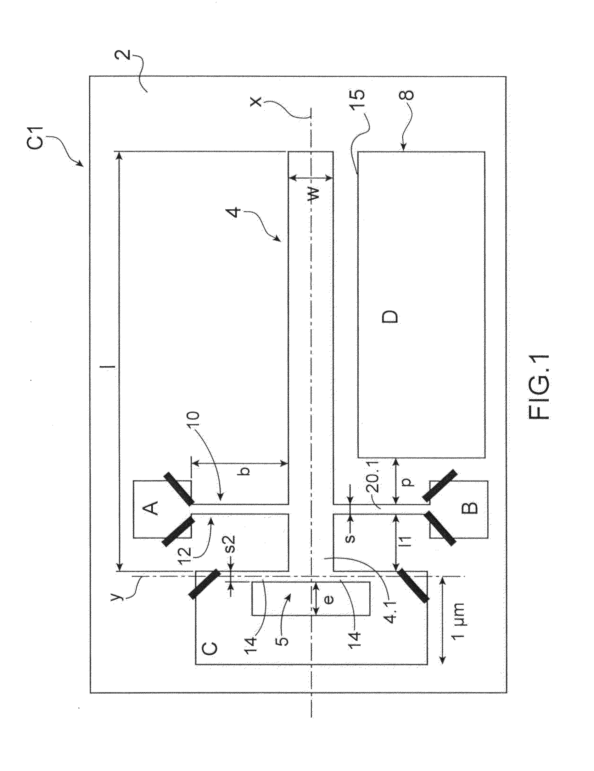
[0124]FIG. 5 shows one alternative embodiment of a sensor according to the The latter C2 differs from the sensor of FIG. 1 by the shape of the suspension means.

[0125]The same references will be used to describe the elements performing the same function and having a close or similar structure.

[0126]The sensor of FIG. 5 comprises an element 4 vibrating relative to a substrate 2 by suspension means formed by two beams 114 connected by a first longitudinal end to the anchoring stud C and by a second longitudinal end to the longitudinal end 4.1 of the moving element. The beams 114 differ from the beams 14 in that their longitudinal axes are inclined relative to the axis X and are concurrent at their second longitudinal end with the axis Z. In the illustrated example, the beams 114 are inclined by an angle of 45° relative to the longitudinal axis X.

[0127]In the examples of FIGS. 1 and 5, the suspension means comprise two beams. It is also possible to consider that they comprise one beam ...

second embodiment

[0151]According to a sensor according to the invention, the heating means are situated away from the vibrating element and the heating takes place by conduction through the gaseous environment.

[0152]FIG. 9 shows an example embodiment of a sensor according to the second embodiment, the sensor C4 further having the particularity of comprising two suspended elements 504, 504′.

[0153]We will describe the vibrating element 504 and the means associated with it in detail; this description also applies to the vibrating element 504′.

[0154]The vibrating element 504 and the associated means are close to those of the sensor of FIG. 1. The vibrating element 504 is made up of a beam with a longitudinal axis X suspended by one of its ends at the substrate by two beams 514 aligned along an axis Y perpendicular to the axis X. Electrostatic excitation means 508 are provided; they comprise an electrode facing a lateral edge of the vibrating element 504. The detection means are formed by a piezoelectric...


PUM

PropertyMeasurementUnit
diameteraaaaaaaaaa
diameteraaaaaaaaaa
temperatureaaaaaaaaaa

Abstract

The invention relates to a thermal flow sensor comprising:
    • a support,
    • at least one element intended to be vibrated relative to the support,
    • suspension means for said vibrating element relative to the vibrating element,
    • means for heating the vibrating element,
    • means for electrostatic excitation of the vibrating element so as to vibrate it at its resonance frequency,
    • piezoelectric gauges for detecting the resonance frequency variation of the vibrating element, the gauges forming means for heating the vibrating element by Joule effect and the suspension means comprising two beams formed by nanowires so as to reduce the heat losses from the vibrating element toward the support.

Description

TECHNICAL FIELD AND BACKGROUND OF THE INVENTION[0001]The present invention relates to a thermal flow sensor implementing at least one nanoelectromechanical resonator (or NEMS for “nanoelectromechanical system”) or microelectromechanical resonator (or MEMS for “microelectromechanical system”), to determine the concentration of the components of a gas from its thermal characteristics, and to a gas sensor comprising at least one such sensor.[0002]A thermal flow sensor refers to any sensor measuring a heat exchange between the body of the sensor and the fluid medium in which the sensor is positioned. This thermal flow sensor is for example a gas sensor or a pressure sensor.[0003]A system capable of determining the analyte composition of a gas may be used to detect and quantify the analytes at the outlet of a chromatography column, more particularly a chromatography micro-column, the latter making it possible to temporarily separate the different gaseous elements of a complex mixture. Th...

Claims


Application Information

Patent Timeline
Patent Type & Authority Applications(United States)
IPC IPC(8): G01F1/66G01N33/00
CPCG01N33/0027G01F1/662G01N25/18G01N27/18G01N29/022G01N30/66
Inventor DURAFFOURG, LAURENTANDREUCCI, PHILIPPECOLINET, ERICJOURDAN, GUILLAUME
Owner COMMISSARIAT A LENERGIE ATOMIQUE ET AUX ENERGIES ALTERNATIVES
Why Eureka
Try Eureka