
Rotor of motor and synchronous motor having the same and wound rotor synchronous motor

a synchronous motor and synchronous motor technology, applied in the direction of magnetic circuit rotating parts, magnetic circuit shape/form/construction, windings, etc., can solve the problems of large amount of additional current needed, inability to control a power factor to 1, and large increase in the cost of ipm motors, so as to reduce the cost of the motor, improve the efficiency of the motor, and reduce the loss of copper.

Inactive Publication Date: 2014-03-20
HYUNDAI MOTOR CO LTD
View PDF0 Cites 17 Cited by
  • Summary
  • Abstract
  • Description
  • Claims
  • Application Information

AI Technical Summary

Benefits of technology

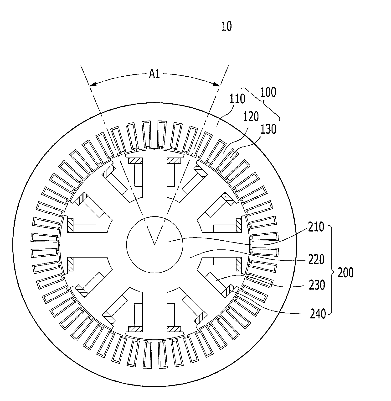
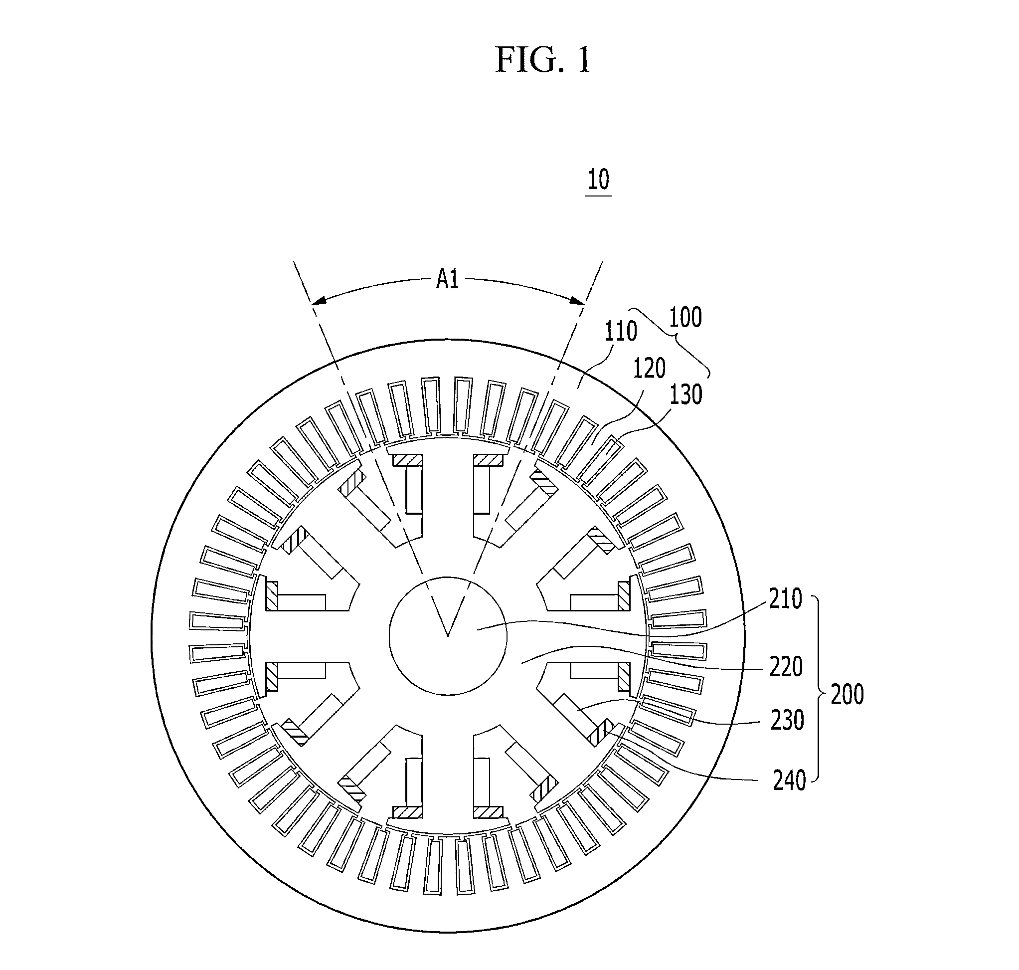
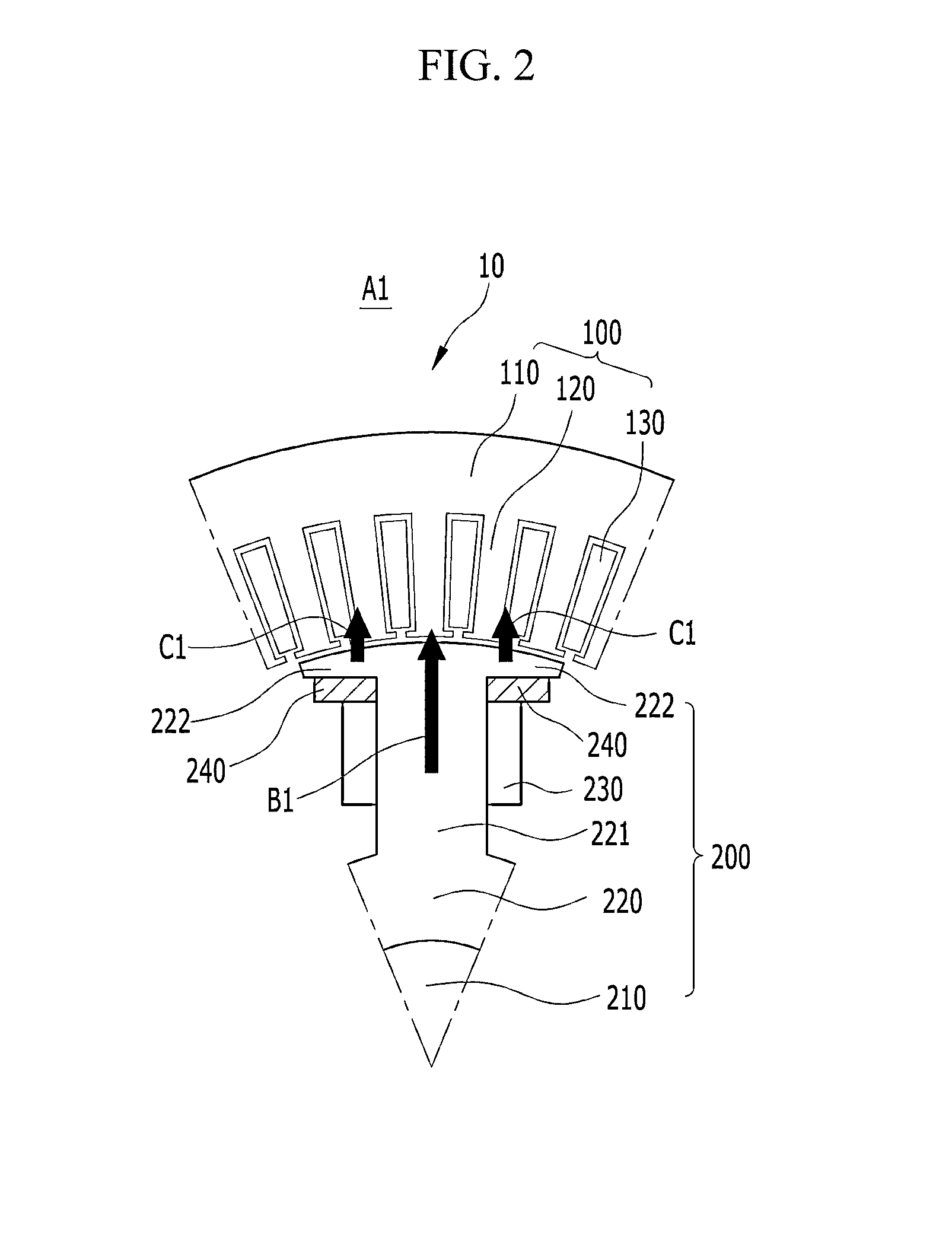
The present invention provides a rotor for a motor that improves energy efficiency and reduces the cost of the motor. The rotor includes a rotation shaft, a core with teeth, a coil, and permanent magnets. The wound rotor synchronous motor using the copper loss reduction technique improves the motor's efficiency by 36%. The invention also replaces the expensive IPM motor with the ferrite magnet and wound rotor combination, reducing the cost of the motor.

Problems solved by technology

Accordingly, it is often impossible to control a power factor to 1, and a cost of the IPM motor increases substantially due to the cost earth rare permanent magnets.
However, in the wound rotor synchronous motor (WRSM), a coil is wound around a rotor instead of the permanent magnet and a large amount of additional current needs to be supplied.
Therefore copper loss often occurs in the coil of the rotor due to the high volume of current therein, thereby deteriorating efficiency.

Method used


Image

  • Rotor of motor and synchronous motor having the same and wound rotor synchronous motor
  • Rotor of motor and synchronous motor having the same and wound rotor synchronous motor
  • Rotor of motor and synchronous motor having the same and wound rotor synchronous motor

Examples


Embodiment Construction

[0021]Hereinafter, exemplary embodiments of the present invention will be described in detail with reference to the accompanying drawings.

[0022]The terminology used herein is for the purpose of describing particular embodiments only and is not intended to be limiting of the invention. As used herein, the singular forms “a,”“an” and “the” are intended to include the plural forms as well, unless the context clearly indicates otherwise. It will be further understood that the terms “comprises” and / or “comprising,” when used in this specification, specify the presence of stated features, integers, steps, operations, elements, and / or components, but do not preclude the presence or addition of one or more other features, integers, steps, operations, elements, components, and / or groups thereof. As used herein, the term “and / or” includes any and all combinations of one or more of the associated listed items.

[0023]It is understood that the term “vehicle” or “vehicular” or other similar term a...


PUM


Abstract

Disclosed is a rotor for a motor in a vehicle. More specifically, the rotor includes a rotation shaft serving as a center of rotation of the rotor, a core installed at the rotation shaft and comprising a plurality of teeth radially protruding with respect to the rotation shaft, a coil wound around the tooth to generate a magnetic field by an external power source, and a pair of permanent magnets installed at both sides of the teeth. Also disclosed is a synchronous motor including the rotor, and a wound rotor synchronous motor.

Description

CROSS-REFERENCE TO RELATED APPLICATION[0001]This application claims priority to and the benefit of Korean Patent Application No. 10-2012-0102852 filed in the Korean Intellectual Property Office on Sep. 17, 2012, the entire contents of which are incorporated herein by reference.BACKGROUND[0002](a) Field of the Invention[0003]The present invention relates to a rotor for a motor around which a coil is wound. Also disclosed is a synchronous motor including the rotor, and a wound rotor synchronous motor.[0004](b) Description of the Related Art[0005]Electric vehicles provide driving power typically from either a DC motor, an induction motor, or a permanent magnet synchronous motor, which are each connected to an appropriate power converter. These motors may be any one of a plurality of configurations. Among them, an internal permanent magnet (IPM) motor capable of obtaining a uniform power operation for a wide range of speeds is primarily used in electric vehicles (EV) and hybrid electric...

Claims


Application Information

Patent Timeline
Patent Type & Authority Applications(United States)
IPC IPC(8): H02K1/22
CPCH02K1/223H02K21/042H02K21/16H02K1/24
Inventor KIM, KYOUNGBUMCHO, HYOUNGJUNMOON, SANGHOONPARK, SANGJINKIM, JUNG SHIK
Owner HYUNDAI MOTOR CO LTD
Learn More