Protection of electro-optic displays against thermal effects

a technology of electro-optic displays and thermal expansion coefficients, applied in the field of protection of electro-optic displays against thermal expansion coefficients, can solve the problems of preventing their widespread use, inadequate service life of these displays, and the serious side effect of distorting gray scale of thermal variation of switching ra

Inactive Publication Date: 2014-03-20
E INK CORPORATION
View PDF4 Cites 100 Cited by
  • Summary
  • Abstract
  • Description
  • Claims
  • Application Information

AI Technical Summary

Benefits of technology

[0028]In another aspect, this invention provides an electrophoretic medium comprising a suspending fluid and a plurality of electrically charged particles suspended in the suspending fluid and capable of moving therethrough upon application of an electrical field to the electrophoretic medium. The suspending fluid contains a compatibilizer to reduce its coefficient of thermal expansion. In one embodiment of this invention, the electrophoretic medium is either encapsulated or of the microcell type. In another embodiment of this invention, the suspending fluid comprises a mixture of an aliphatic hydrocarbon and a chlorinated hydrocarbon, and the compatibilizer comprises a fluorocarbon.

Problems solved by technology

Nevertheless, problems with the long-term image quality of these displays have prevented their widespread usage.
For example, particles that make up electrophoretic displays tend to settle, resulting in inadequate service-life for these displays.
Encapsulated electrophoretic media are typically capable of achieving gray scale, and in such gray scale media, thermal variation of the switching rate can have the serious side effect of distorting gray scale.
Similar problems are encountered with other types of electro-optic media.
The problems caused by temperature changes in electro-optic media are exacerbated if the temperature of the display becomes non-uniform, since the switching characteristics, and the gray scale “drift” discussed above, will then vary from point to point within the display.
Unfortunately, it is often necessary or desirable to mount electro-optic media in close proximity to heat generating components.
Electro-optic displays often require substantial amounts of electrical circuitry.
(Such rear mounting of electronic circuitry is of course not possible in displays using transmissive electro-optic media, such as conventional liquid crystals, since the electronic circuitry would be visible as shadows or dark areas on the display.)
However, rear mounting the electronic circuitry leads to heat flow from heat generating components (such as logic chips and perhaps batteries) to the electro-optic medium, thus causing non-uniform heating of the medium, with the aforementioned deleterious effects on image quality.
There is another thermal problem encountered in encapsulated and microcell electrophoretic displays, namely that the thermal expansion of the suspending fluid within the capsules or microcells exceeds that the walls surrounding the capsules or microcells, thus causing mechanical strains within the electrophoretic medium.
In many cases, the maximum temperature which an encapsulated or microcell electrophoretic medium can tolerate is limited by these mechanical strains, which at high temperatures can become so great that the capsules or microcells rupture, permitting the internal phase comprising the electrophoretic particles and suspending fluid to escape and rendering the affected portions of the medium non-functional.
This capsule / microcell bursting problem can be experienced while the display is in use, but tends to be a greater problem during manufacture of displays.
Depending upon the exact components used in the display, the lamination may have to be conducted under heat and / or pressure, and this heat and / or pressure may cause the aforementioned capsule / microcell bursting problem.
This bursting problem is exacerbated by the types of suspending fluids used in many electrophoretic media.

Method used


Image

  • Protection of electro-optic displays against thermal effects
  • Protection of electro-optic displays against thermal effects
  • Protection of electro-optic displays against thermal effects

Examples


Embodiment Construction

[0032]As already indicated, the present invention relates to two discrete methods for protection of electro-optic displays against thermal effects. These two methods can be used alone or in combination, but for convenience will hereinafter be described separately.

[0033]Provision of Heat Shield

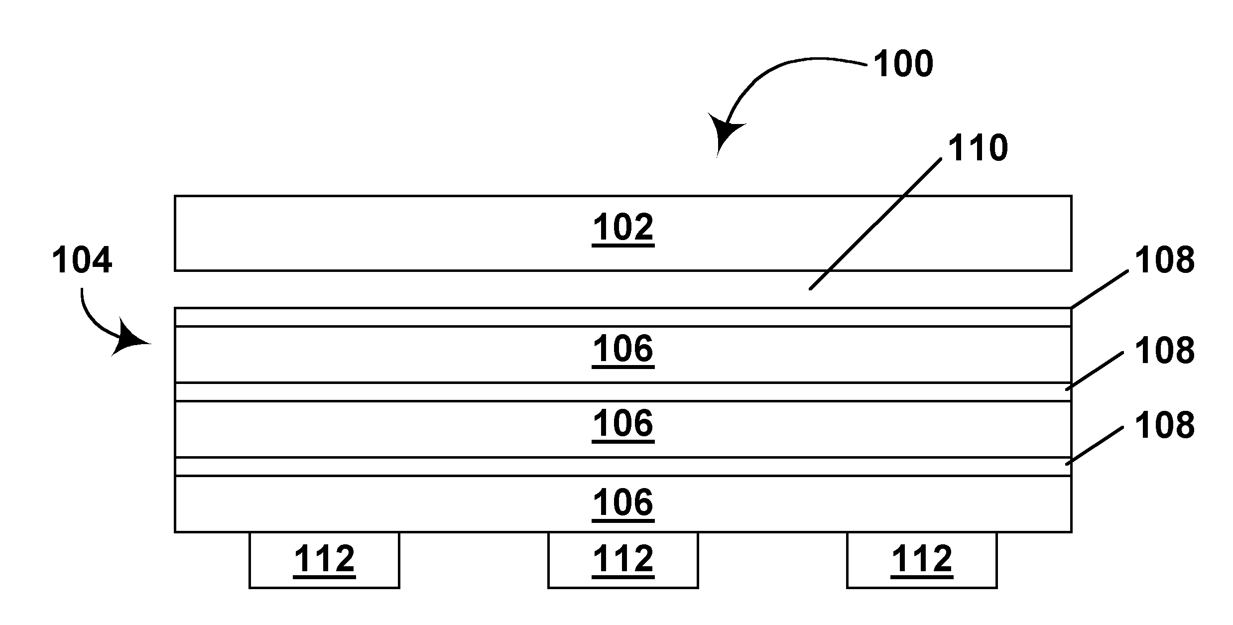
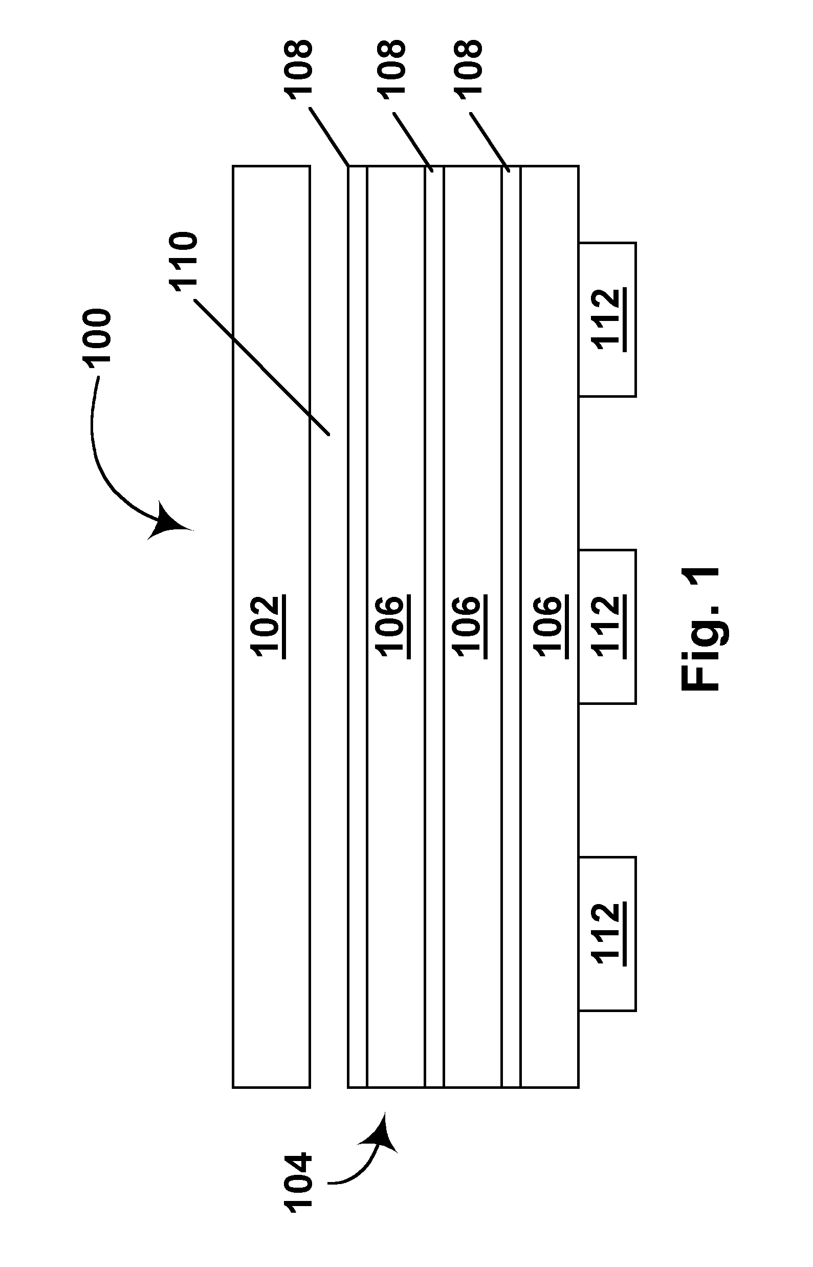
[0034]As already mentioned, in one aspect this invention provides an electro-optic display having a heat shield disposed between a heat generating component and a layer of electro-optic material, this heat shield comprising a layer of thermally insulating material and a layer of thermally conducting material disposed between the layer of thermally insulating material and the layer of electro-optic material.

[0035]The heat generating component of the present electro-optic display may be of any known type. The component may be, for example an alternating current / direct current conversion component, such as a transformer, or another type of power supply or battery; all batteries generate some heat ...


PUM

PropertyMeasurementUnit
coefficient of thermal expansionaaaaaaaaaa
electrophoreticaaaaaaaaaa
weightaaaaaaaaaa

Abstract

An electro-optic display comprises a layer of reflective electro-optic material capable of changing its optical state on application of an electric field, an electrode, a heat generating component in heat conducting relationship with the electro-optic material, and a heat shield disposed between the heat generating component and the electro-optic material, the heat shield comprising a layer of thermally insulating material and a layer of thermally conducting material, the thermally conducting material being disposed between the thermally insulating material and the electro-optic material. The invention also provides an electrophoretic medium comprising a suspending fluid and a plurality of electrically charged particles suspended in the suspending fluid and capable of moving therethrough upon application of an electrical field to the electrophoretic medium, the suspending fluid containing a compatibilizer to reduce its coefficient of thermal expansion.

Description

REFERENCE TO RELATED APPLICATIONS[0001]This application is a division of copending application Ser. No. 10 / 604,630, filed Aug. 6, 2003 (Publication No. 2004 / 0105036), which itself claims priority from Provisional Application Ser. No. 60 / 319,450 filed Aug. 6, 2002. The entire disclosure of this provisional application, and of all U.S. patents and applications mentioned below, are herein incorporated by reference.BACKGROUND OF INVENTION[0002]This invention relates to protection of electro-optic displays against thermal effects. More specifically, this invention relates to methods for reducing the thermal expansion coefficients of the suspending fluid used in electrophoretic media, and to methods for shielding electro-optic media against heat generated in electronic components located adjacent the media.[0003]Electro-optic displays comprise a layer of electro-optic material, a term which is used herein in its conventional meaning in the art to refer to a material having first and secon...

Claims


Application Information

Patent Timeline
Patent Type & Authority Applications(United States)
IPC IPC(8): G09G3/20B29C65/54G02F1/01G02F1/133G02F1/167
CPCG02F1/0147G02F1/133382G02F1/167
Inventor PAOLINI, JR., RICHARD J.ZHANG, LIBING
Owner E INK CORPORATION
Why Eureka
Try Eureka