High efficiency lighting device including one or more solid state light emitters, and method of lighting

a lighting device and solid-state technology, applied in the field of lighting devices, can solve the problems of incandescent light bulbs being very energy-inefficient light sources, incandescent light bulbs having relatively short lifetimes, and still less efficient than solid-state light emitters such as light emitting diodes, so as to reduce cri ra, improve efficiency, and improve efficiency.

Active Publication Date: 2014-03-20
IDEAL IND LIGHTING LLC
View PDF6 Cites 192 Cited by
  • Summary
  • Abstract
  • Description
  • Claims
  • Application Information

AI Technical Summary

Benefits of technology

[0057]In comparison to some available lighting devices, some embodiments of lighting devices in accordance with the present inventive subject matter have moderately reduced CRI Ra (for example, in some embodiments, in the range of 84 to 86, or in some cases in the range of 75 to 85, e.g., about 80), but they provide excellent efficiency. In such instances, despite the moderate reduction in CRI Ra, such devices, with their increased efficiency, can be used in situations where the moderately reduced CRI Ra is acceptable (or deemed to be acceptable), and / or in situations where even more significantly reduced CRI Ra would not be considered to be a problem (for example, in some general illumination, security lighting, street lighting and / or emergency lighting).

Problems solved by technology

It is well known that incandescent light bulbs are very energy-inefficient light sources—about ninety percent of the electricity they consume is released as heat rather than light.
Fluorescent light bulbs are more efficient than incandescent light bulbs (by a factor of about 10) but are still less efficient than solid state light emitters, such as light emitting diodes.
In addition, as compared to the normal lifetimes of solid state light emitters, e.g., light emitting diodes, incandescent light bulbs have relatively short lifetimes, i.e., typically about 750-1000 hours.
Fluorescent bulbs have longer lifetimes than incandescent lights (e.g., fluorescent bulbs typically have lifetimes of 10,000-20,000 hours), but provide less favorable color reproduction.
The impact of the need to replace light emitters is particularly pronounced where access is difficult (e.g., vaulted ceilings, bridges, high buildings, highway tunnels) and / or where change-out costs are extremely high.

Method used


Image

  • High efficiency lighting device including one or more solid state light emitters, and method of lighting
  • High efficiency lighting device including one or more solid state light emitters, and method of lighting
  • High efficiency lighting device including one or more solid state light emitters, and method of lighting

Examples


first embodiment

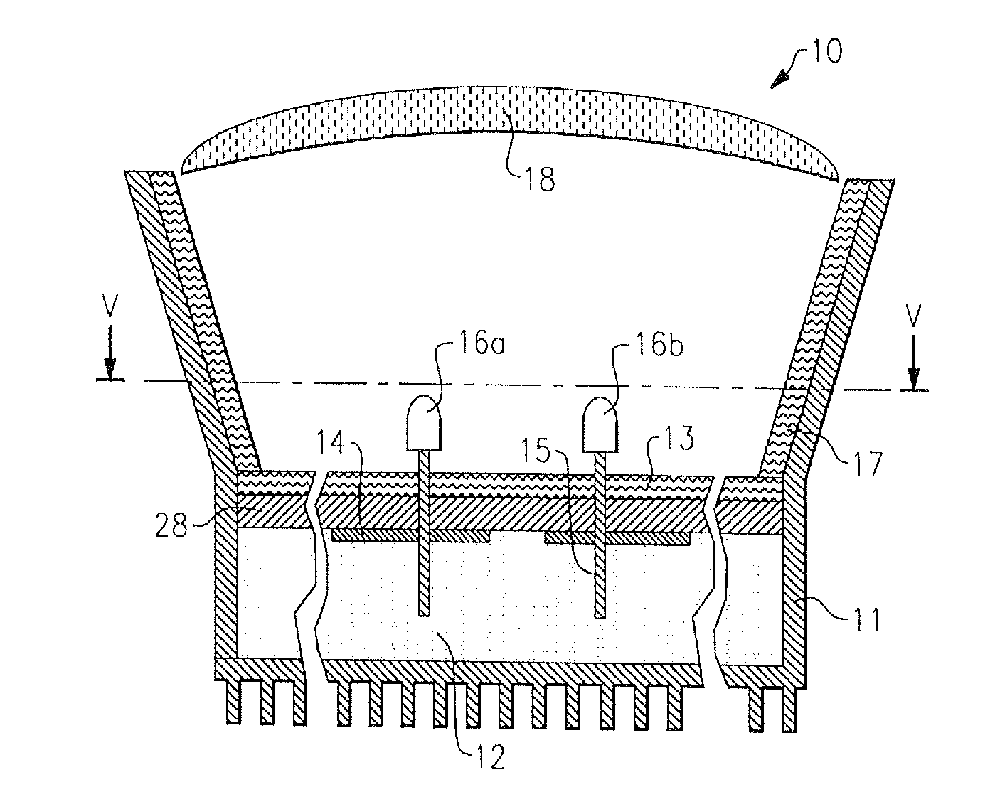
[0348]FIG. 1 depicts a lighting device in accordance with the present inventive subject matter.

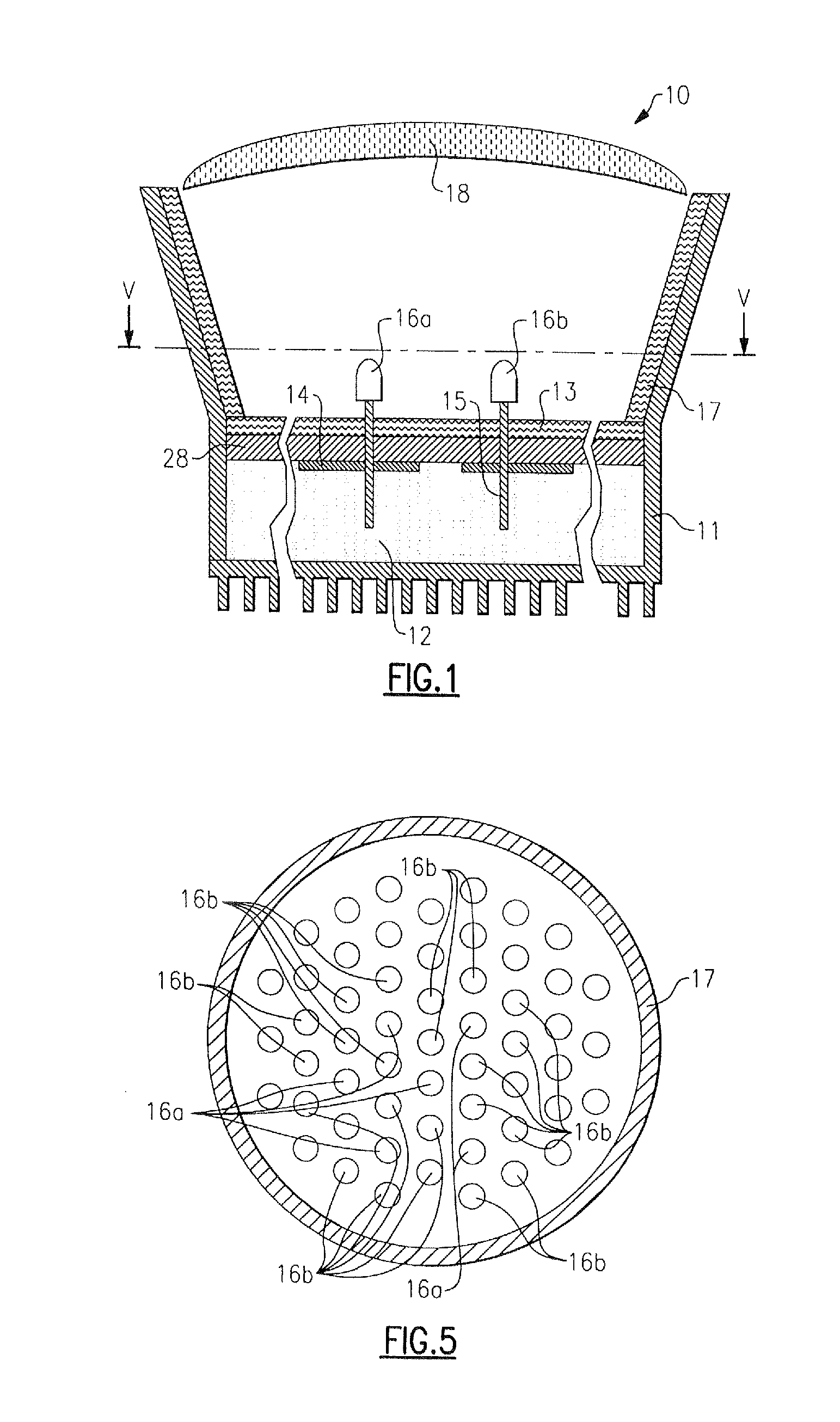
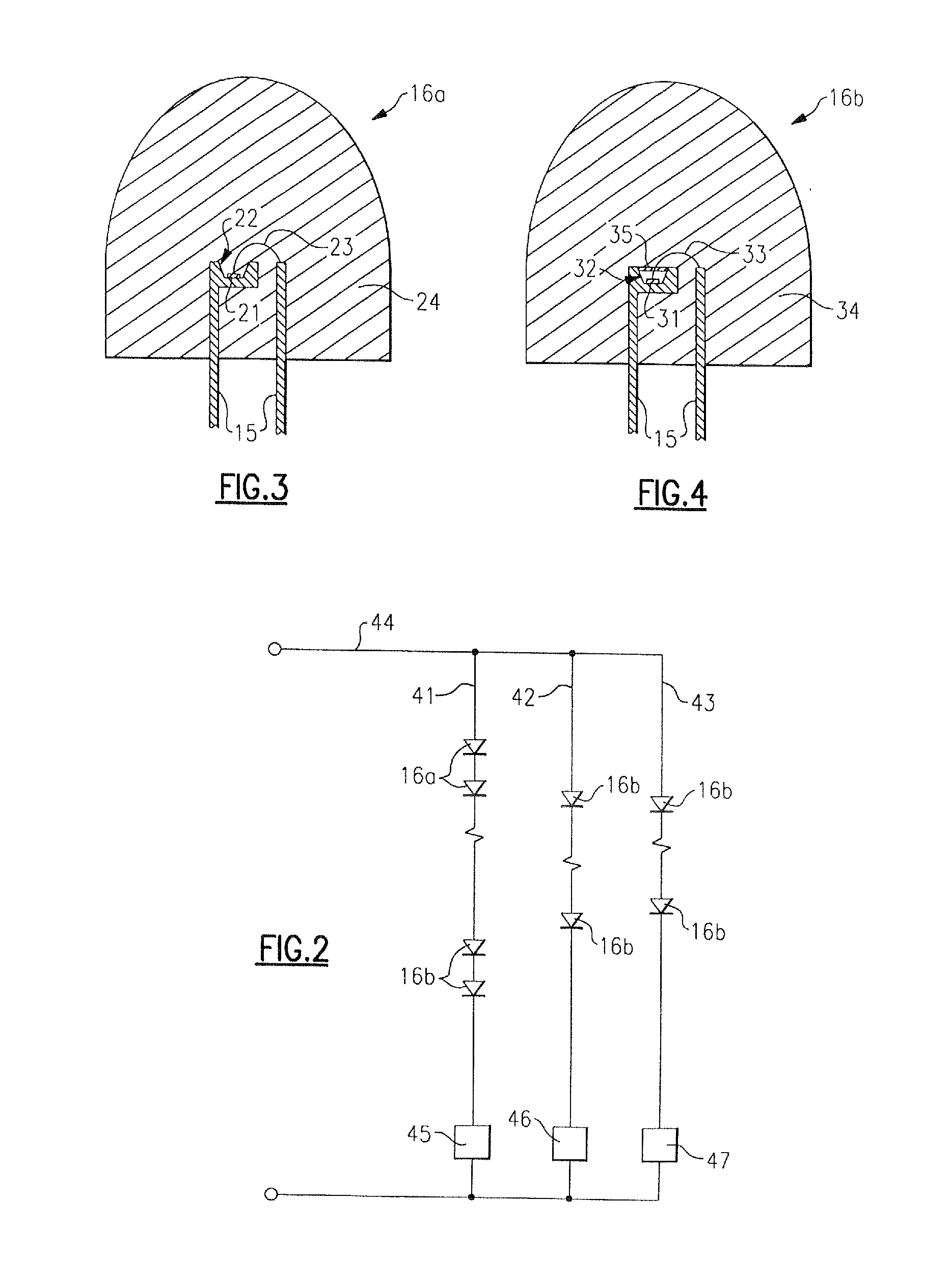
[0349]Referring to FIG. 1, there is shown a lighting device 10 that includes a heat spreading element 11 (formed of aluminum), electrically insulating regions 12 (comprising any desired material which is thermally conductive and not electrically conductive, a wide variety of which are well-known to those skilled in the art, e.g., ceramic, epoxy or silicone optionally filled with silicon carbide, diamond, cubic boron nitride, alumina, etc), a highly reflective surface 13 (which can be formed in situ by polishing the surface of the aluminum heat spreading element, or made of MCPET® (marketed by Furukawa, a Japanese corporation)), conductive traces 14 formed of copper, lead frames 15 formed of silver-plated copper (or silver-plated mild steel), packaged LEDs 16a, 16b (described in more detail below), a reflective cone 17 (made of MCPET®) with a diffuse light scattering surface and a diffusing...

second embodiment

[0380]FIG. 6 is a schematic diagram of a high efficiency lamp 150 in accordance with the inventive subject matter. The lamp 150 includes a lower housing 151 and an upper housing 152, greenish-yellowish emitters 163 and red light emitting diodes 164. The lower housing 151 is a cast aluminum housing having fins surrounding the circumference and provides sidewalls of the mixing enclosure 158. The lower housing may be a lower housing of an LR6 fixture from Cree, Inc., Durham, N.C., with the trim flange removed such that the housing does not extend past the lens 157. Other suitable lower housing materials having similar thermal properties could also be utilized. The lower housing 151 and the lens 157, in combination, comprise an enclosing structure that surrounds the greenish-yellowish emitters 163 and the red light emitting diodes 164.

[0381]The upper housing 152 includes a cavity 153 and also has fins to increase the overall area for heat extraction. In the present embodiment, the uppe...


PUM


Abstract

A lighting device comprising first and second groups of solid state light emitters, that emit light having approximate dominant wavelength (in nm) of 441-448 (or 442-450, 444-455, 444-446, 442-445 or 444-452) and 555 nm to 585 nm, respectively. If the first and second groups are illuminated, a mixture of light would, in the absence of any additional light, have a color point within one or more of first, second, third, fourth and fifth areas on the 1931 CIE Chromaticity Diagram. In some embodiment, the lighting device further comprises a third group that emits light having approximate dominant wavelength (in nm) of 600-640 (or 605-610, 605-607, 600-606, 602-606 or 615-620). Also, methods of lighting.

Description

CROSS-REFERENCE TO RELATED APPLICATIONS[0001]This application claims the benefit of U.S. Provisional Patent Application No. 61 / 701,027, filed Sep. 14, 2012, the entirety of which is incorporated herein by reference as if set forth in its entirety.[0002]This application claims the benefit of U.S. Provisional Patent Application No. 61 / 758,081, filed Jan. 29, 2013, the entirety of which is incorporated herein by reference as if set forth in its entirety.FIELD OF THE INVENTIVE SUBJECT MATTER[0003]The present inventive subject matter relates to a lighting device, in particular, a device that includes one or more solid state light emitters.[0004]The present inventive subject matter also relates to a lighting device, in particular, a device which includes one or more light emitting diodes and one or more luminescent materials (e.g., one or more phosphors).[0005]The present inventive subject matter is also directed to lighting methods.BACKGROUND[0006]There is an ongoing effort to develop sy...

Claims


Application Information

Patent Timeline
Patent Type & Authority Applications(United States)
IPC IPC(8): F21K99/00
CPCF21K9/54F21K9/62
Inventor PICKARD, PAUL KENNETHTAYLOR, JASONVAN DE VEN, ANTONY PAUL
Owner IDEAL IND LIGHTING LLC
Why Eureka
Try Eureka