Silicon-carbon-nitride selective etch

a silicon carbon nitride and selective etching technology, applied in the direction of basic electric elements, electrical equipment, electric discharge tubes, etc., can solve the problem of few options for selective etching of silicon carbon nitride, and achieve the effect of faster ra

Active Publication Date: 2014-03-20
APPLIED MATERIALS INC
View PDF9 Cites 183 Cited by
  • Summary
  • Abstract
  • Description
  • Claims
  • Application Information

AI Technical Summary

Benefits of technology

[0005]A method of etching exposed silicon-nitrogen-and-carbon-containing material on patterned heterogeneous structures is described and includes a remote plasma etch formed from a fluorine-containing precursor and an oxygen-containing precursor. Plasma effluents from the remote plasma are flowed into a substrate processing region where the plasma effluents react with the exposed regions of silicon-nitrogen-and-carbon-containing material. The plasma effluents react with the patterned heterogeneous structures to selectively remove silicon-nitrogen-and-carbon-containing material from the exposed silicon-nitrogen-and-carbon-containing material regions while very slowly removing selected other exposed materials. The silicon-nitrogen-and-carbon-containing material selectivity results partly from the presence of an ion suppression element positioned between the remote plasma and the substrate processing region. The ion suppression element controls the number of ionically-charged species that reach the substrate. The methods may be used to selectively remove silicon-nitrogen-and-carbon-containing material at a faster rate than exposed silicon oxide or exposed silicon nitride.

Problems solved by technology

However, there are few options for selectively etching silicon carbon nitride.

Method used


Image

  • Silicon-carbon-nitride selective etch
  • Silicon-carbon-nitride selective etch
  • Silicon-carbon-nitride selective etch

Examples


Embodiment Construction

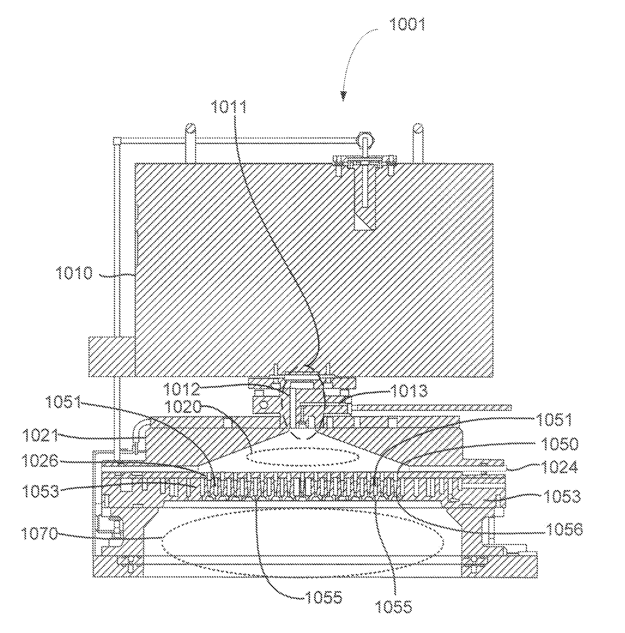
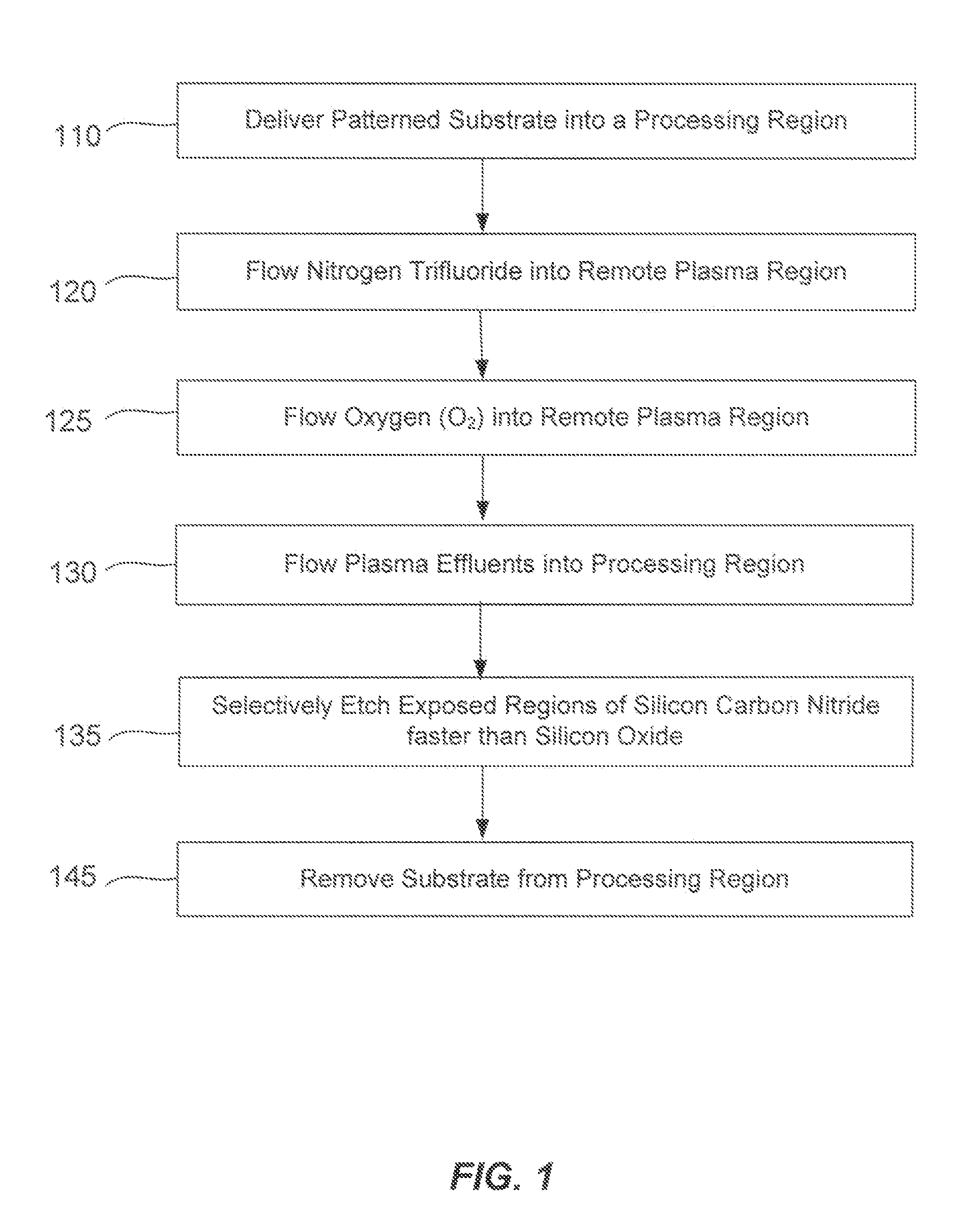
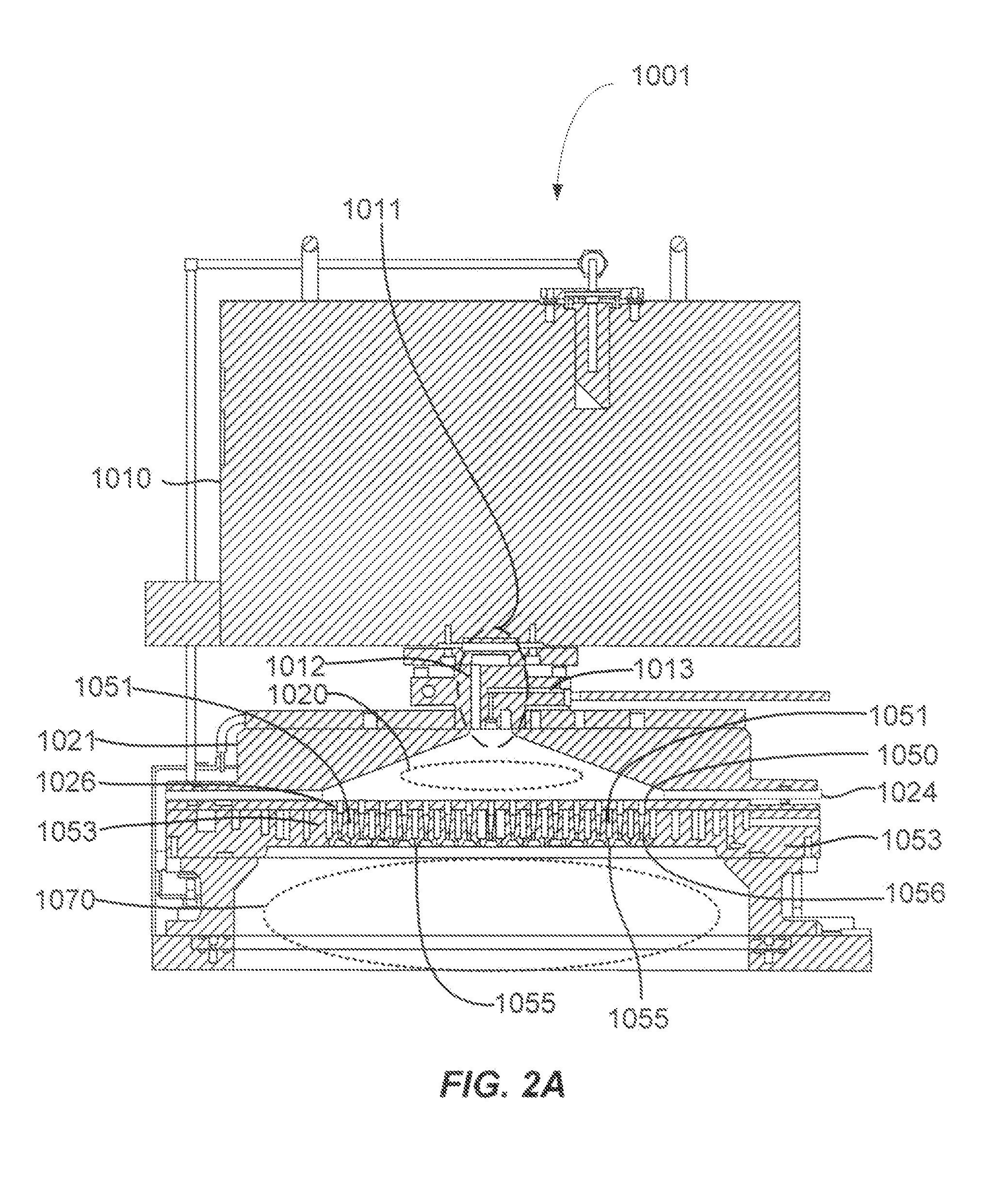
[0014]A method of etching exposed silicon-nitrogen-and-carbon-containing material on patterned heterogeneous structures is described and includes a remote plasma etch formed from a fluorine-containing precursor and an oxygen-containing precursor. Plasma effluents from the remote plasma are flowed into a substrate processing region where the plasma effluents react with the exposed regions of silicon-nitrogen-and-carbon-containing material. The plasma effluents react with the patterned heterogeneous structures to selectively remove silicon-nitrogen-and-carbon-containing material from the exposed silicon-nitrogen-and-carbon-containing material regions while very slowly removing selected other exposed materials. The silicon-nitrogen-and-carbon-containing material selectivity results partly from the presence of an ion suppression element positioned between the remote plasma and the substrate processing region. The ion suppression element controls the number of ionically-charged species t...


PUM


Abstract

A method of etching exposed silicon-nitrogen-and-carbon-containing material on patterned heterogeneous structures is described and includes a remote plasma etch formed from a fluorine-containing precursor and an oxygen-containing precursor. Plasma effluents from the remote plasma are flowed into a substrate processing region where the plasma effluents react with the exposed regions of silicon-nitrogen-and-carbon-containing material. The plasma effluents react with the patterned heterogeneous structures to selectively remove silicon-nitrogen-and-carbon-containing material from the exposed silicon-nitrogen-and-carbon-containing material regions while very slowly removing selected other exposed materials. The silicon-nitrogen-and-carbon-containing material selectivity results partly from the presence of an ion suppression element positioned between the remote plasma and the substrate processing region. The ion suppression element controls the number of ionically-charged species that reach the substrate. The methods may be used to selectively remove silicon-nitrogen-and-carbon-containing material at a faster rate than exposed silicon oxide or exposed silicon nitride.

Description

CROSS-REFERENCES TO RELATED APPLICATIONS[0001]This application claims the benefit of U.S. Prov. Pat App. No. 61 / 703,612 filed Sep. 20, 2012, and titled “SILICON-CARBON-NITRIDE SELECTIVE ETCH,” which is incorporated in its entirety herein by reference for all purposes.BACKGROUND OF THE INVENTION[0002]Integrated circuits are made possible by processes which produce intricately patterned material layers on substrate surfaces. Producing patterned material on a substrate requires controlled methods for removal of exposed material. Chemical etching is used for a variety of purposes including transferring a pattern in photoresist into underlying layers, thinning layers or thinning lateral dimensions of features already present on the surface. Often it is desirable to have an etch process which etches one material faster than another helping e.g. a pattern transfer process proceed. Such an etch process is said to be selective to the first material. As a result of the diversity of materials,...

Claims


Application Information

Patent Timeline
Patent Type & Authority Applications(United States)
IPC IPC(8): H01L21/311
CPCH01L21/31116H01J37/32357H01L21/76802
Inventor CHEN, ZHIJUNZHANG, JINGCHUNWANG, ANCHUANINGLE, NITIN K.
Owner APPLIED MATERIALS INC
Why Eureka
Try Eureka