
Transcutaneous Implant for Skeletal Attachment of External Prosthetic Devices

a prosthetic device and implant technology, applied in the field of transcutaneous implant for skeletal attachment of external prosthetic devices, can solve the problems of poor proprioception of users, inability to adapt to the prosthetic interface, so as to facilitate the extraction of bone components, facilitate the connection of the prosthetic interface to the bone anchorage, and facilitate the effect of extraction

Inactive Publication Date: 2014-03-20
ZIMMER INC
View PDF19 Cites 21 Cited by
  • Summary
  • Abstract
  • Description
  • Claims
  • Application Information

AI Technical Summary

Benefits of technology

The patent text describes implantable devices that connect an external prosthetic device to bone. The devices have a two-piece design with a bone anchor and a prosthetic interface. The prosthetic interface is placed outside the bone passage but reliably connected to the bone anchor in a transcutaneous manner. The connection can be made using a fastener or a press-fit connection between the interfaces. The text also mentions that the design is compatible with failure load, which means that if there is a mechanical failure at the prosthetic interface, the damaged part can be replaced without replacing the entire implant. This design allows for easier maintenance and replacement of prosthetic parts.

Problems solved by technology

There are a number of significant disadvantages with such a configuration.
First, skin breakdown is common as the soft-tissue / socket interface may create excessive pressure areas on the skin.
The transmission of forces from the skeleton through the soft tissues is an energy inefficient process.
Users having poorly fitting prostheses with this interface tend to lack proprioception, particularly as the standard prostheses do not tend to convey tactile feedback during use.

Method used


Image

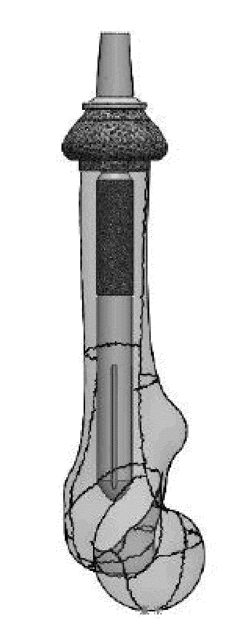
  • Transcutaneous Implant for Skeletal Attachment of External Prosthetic Devices
  • Transcutaneous Implant for Skeletal Attachment of External Prosthetic Devices
  • Transcutaneous Implant for Skeletal Attachment of External Prosthetic Devices

Examples


example 1

Two-Piece Transcutaneous Device

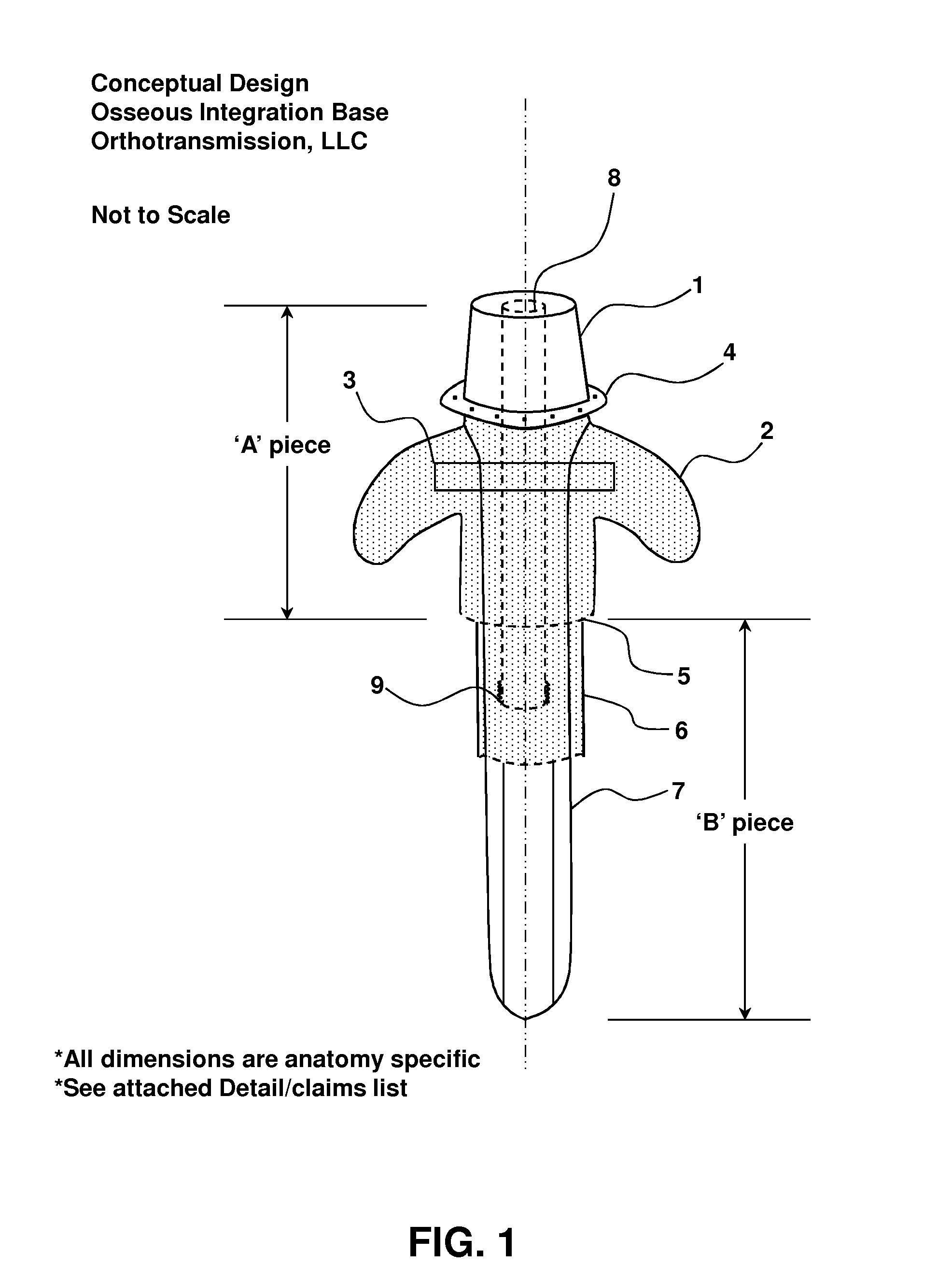
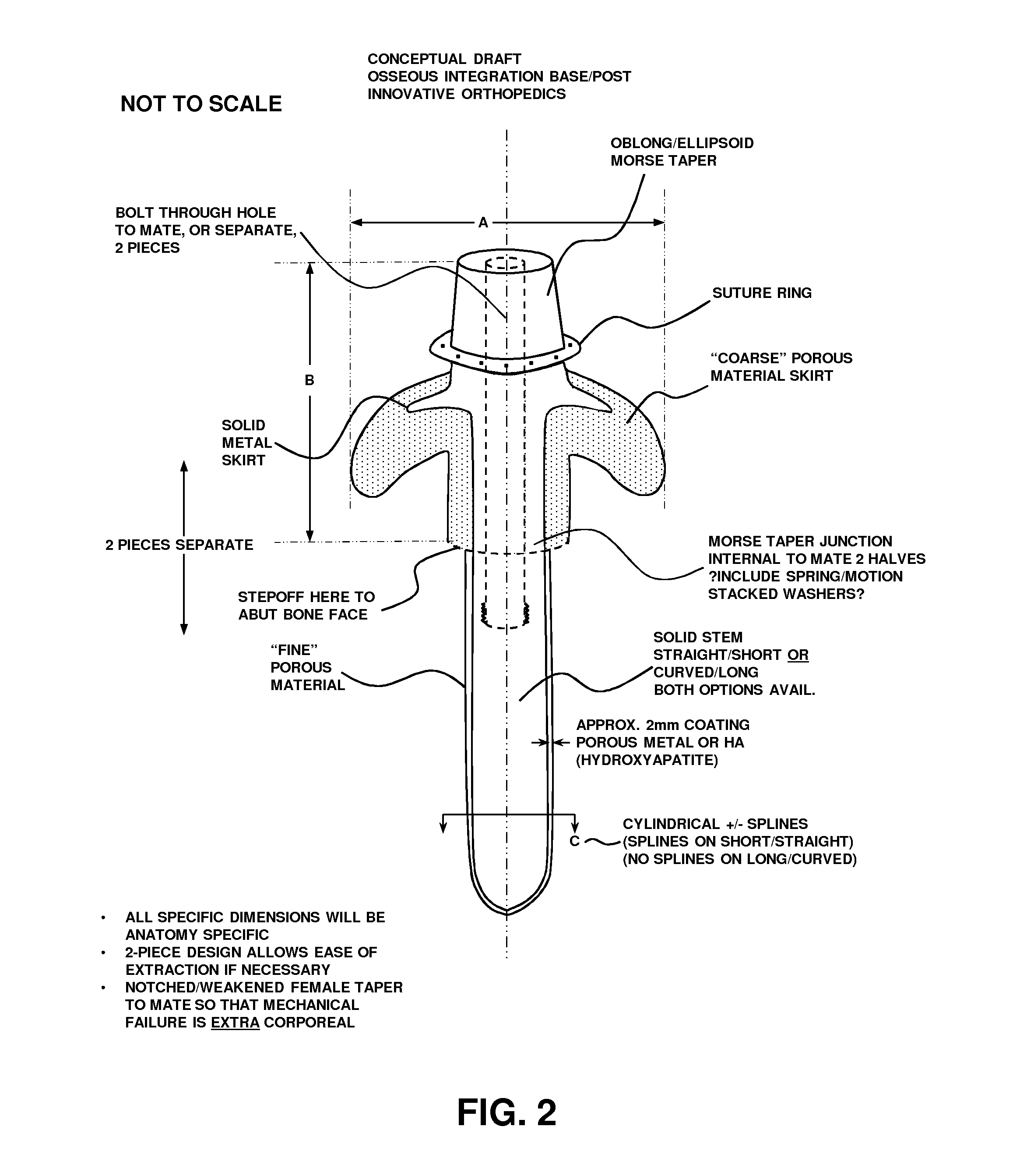
[0077]FIGS. 1-2 illustrate a two-piece transcutaneous device designed to provide a bone anchor in the bone of a residual limb or digit in an animal (human or non-human) for direct skeletal attachment of an external prosthetic device. The device uses highly porous coating along the majority of its length to act as a matrix for biologic ingrowth of various tissues.

[0078]The biologic ingrowth at the bone interface (in and around 5 of FIG. 1) is bony and facilitates rigid, stable, and durable fixation of the implant to the bone. The biologic ingrowth in the soft tissues in and around 2 (skin, subcutaneous tissue, muscle) provides an effective barrier against infection at the bone / implant interface due to its vascularity—making available white blood cells and antibiotic delivery via blood vessels if necessary to ward off advancing bacteria.

[0079]The device is illustrated as two separate pieces, ‘A’ Piece (“prosthetic interface”) and ‘B’ Piece (“bone anchor”...

example 2

Prosthesis for Transfemoral Amputees

[0090]An example of a prosthesis for use by transfemoral amputees is illustrated in FIG. 3. The overall system can be characterized into different subsystems: the patient 10 (residual limb), implant 20, prosthesis 40 and, optionally, a failsafe 30 that operably connects the prosthesis 40 to the implant 20, including any of the two-piece transcutaneous devices disclosed herein. The failsafe functions as an interface between the prosthesis and the implant and, therefore, the patient; in particular the bone that surrounds the bone-implanted portion of the implant. As further discussed below, system load is empirically measured by force or pressure transducers, computationally determined such as by finite element analysis, and / or obtained from the literature. In this manner, the loads exerted on bone by the implant in various settings are determined. With such loads known, as well as the strength of patient's tissue such as bone strength and bone fail...

example 3

Failsafe

[0117]Examples of a failsafe 30 (see FIG. 3) for use between the prosthesis and the implant is provided in FIGS. 20 and 32. The failsafe, also referred to as failsafe mechanism or failsafe element, is designed to ensure that dangerous loads are not transmitted to the body, thereby avoiding possible harm such as bone fracture and / or bone anchor damage requiring surgical removal and replacement. Another example is provided in U.S. Pat. Pub. No. 2008 / 0058957. The implant provided herein may use any failsafe. The failsafe is preferably reliable, simple and easy to use. FIG. 20A shows one option for a failsafe based on controlled material properties, such as a shear pin and two notches. The shear pin 2000 is designed to fail in torsion while the notches 2010 are designed to fail in bending, in this case posterior / anterior and / or medial / lateral directions. Another failsafe option is provided in FIG. 20B that relies on a mechanical system having a plurality of springs 2020 connecte...


PUM


Abstract

Provided herein are devices and methods for connecting a transcutaneous external prosthetic device to a bone, such as a bone of an amputee. The device is a two-piece transcutaneous implant device to provide reversible connection for ease of implantation, reliability, and relatively easy access for removal, while maximizing tissue ingrowth to reduce risk of infection and attendant adverse outcomes. The devices provided herein comprise a prosthetic interface and a bone anchor. A through-hole that traverses a longitudinal length of the prosthetic interface and at least a longitudinal portion of the bone anchor receives a fastener to reversibly connect the prosthetic interface to the bone anchor implanted in bone. A connector may connect to a failsafe element which, in turn, connects to an external prosthetic device.

Description

CROSS-REFERENCE TO RELATED APPLICATIONS[0001]This application claims benefit to U.S. Provisional Patent Application Nos. 61 / 698,866, filed Sep. 10, 2012 and 61 / 820,264 filed May 7, 2013, each of which are incorporated by reference to the extent not inconsistent herewith.BACKGROUND OF THE INVENTION[0002]Provided herein are devices and related methods for mechanically connecting an external prosthetic device to a user's skeleton via a transcutaneous implant.[0003]Currently, amputees are most commonly fit with a socket interface prosthesis, with the socket contoured to fit the individual's residual limb. In this manner, the socket interface transmits forces from the appendicular skeleton through the soft tissues to the prosthesis. There are a number of significant disadvantages with such a configuration. First, skin breakdown is common as the soft-tissue / socket interface may create excessive pressure areas on the skin. The transmission of forces from the skeleton through the soft tissu...

Claims


Application Information

Patent Timeline
Patent Type & Authority Applications(United States)
IPC IPC(8): A61F2/78
CPCA61F2/78A61F2/2814A61F2002/6845A61F2002/7887A61F2/30771A61F2002/30011A61F2002/30028A61F2002/30884A61F2002/3092A61F2002/3093
Inventor HUGATE, RONALD
Owner ZIMMER INC
Learn More