
Structure of built-in self-test for pressure tester and method thereof

Active Publication Date: 2014-03-27
KING YUAN ELECTRONICS
View PDF3 Cites 3 Cited by
  • Summary
  • Abstract
  • Description
  • Claims
  • Application Information

AI Technical Summary

Benefits of technology

The present invention provides a method for testing pressure using a built-in self-test structure. The method includes steps of applying an input voltage to the structure, heating up to increase pressure in the cavity, and monitoring the small deformation of the membrane layers. The technical effect of this invention is to provide a reliable and efficient means for testing pressure.

Problems solved by technology

On the other hand, the overall cost is difficult to reduce due to the high cost of using the high-priced test equipment.
In the conventional testing method, the test equipment is used to build up a vacuum cavity or provide an external pressure to detect the device, and therefore it is unable to effectively reduce the testing cost, which makes it difficult to increase the market share and maximize profit.

Method used


Image

  • Structure of built-in self-test for pressure tester and method thereof
  • Structure of built-in self-test for pressure tester and method thereof
  • Structure of built-in self-test for pressure tester and method thereof

Examples


Embodiment Construction

[0019]The detailed description of the present invention will be discussed in the following embodiments, which are not intended to limit the scope of the present invention, and can be adapted for other applications. While drawings are illustrated in detail, it is appreciated that the quantity of the disclosed components may be greater or less than that disclosed, except where expressly restricting the amount of the components.

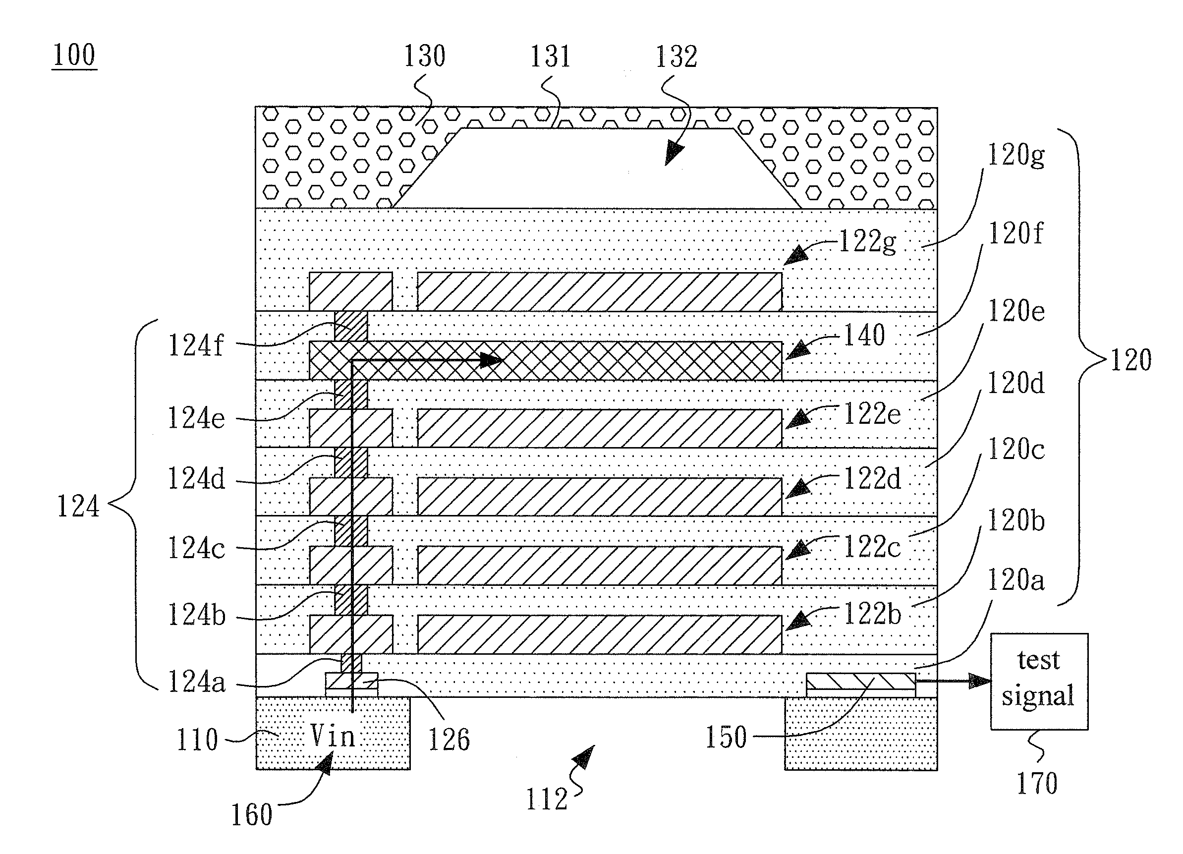
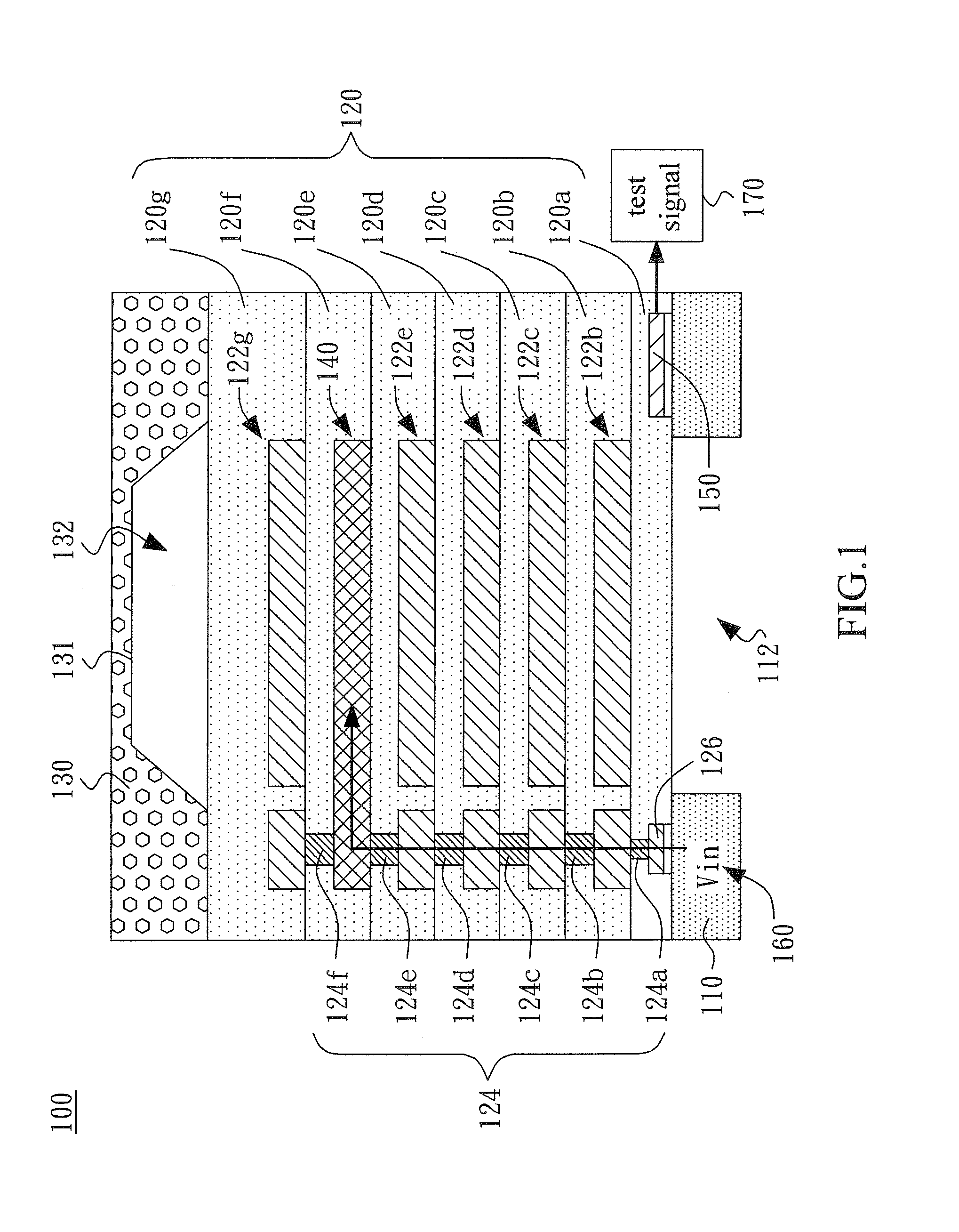
[0020]Referring to FIG. 1, FIG. 1 shows a cross-sectional view of a built-in self-test structure 100 for a pressure tester according to an embodiment of the invention. The built-in self-test structure 100 includes a substrate 110, a plurality of membrane layers 120, a fixing portion 130, an electrical heating unit 140 and a sensing circuit unit 150. The membrane layers 120 are formed on the substrate 110. The fixing portion 130 is configured on the membrane layers 120. The fixing portion 130 includes a notch 131, and the notch 131 and the membrane layers 120 def...


PUM


Abstract

A built-in self-test structure for a pressure tester and a method thereof are provided. The built-in self-test structure includes a substrate, a plurality of membrane layers, a fixing portion, an electrical heating unit and a sensing circuit unit. The membrane layers are formed on the substrate. The fixing portion is configured on the membrane layers and includes a notch. The notch and the membrane layers define a cavity. The electrical heating unit is configured on one membrane layer, and the sensing circuit unit is configured on another membrane layer. The electrical heating unit heats up to increase the pressure in the cavity according to an input voltage, so that the membrane layers have a small deformation. The sensing circuit unit outputs a test signal according to the small deformation.

Description

CROSS-REFERENCE TO RELATED APPLICATIONS[0001]The entire contents of Taiwan Patent Application No. 101135132, filed on Sep. 25, 2012, from which this application claims priority, are incorporated herein by reference.BACKGROUND OF THE INVENTION[0002]1. Field of the Invention[0003]The present invention generally relates to a built-in self-test structure for a pressure tester, and more particularly to a built-in self-test structure for the wafer-level pressure tester to effectively reduce the testing cost and improve the testing efficiency.[0004]2. Description of Related Art[0005]As the micro-electromechanical system (MEMS) device is widely used in many applications and the semiconductor technology has also become mature gradually, the price of the MEMS device has been decreased. On the other hand, the overall cost is difficult to reduce due to the high cost of using the high-priced test equipment.[0006]More particularly, a general test of wafer-level devices must need the specific test...

Claims


Application Information

Patent Timeline
IPC IPC(8): G01L27/00
CPCG01L27/00
Inventor CHENG, WEI-JEN
Owner KING YUAN ELECTRONICS
Features
  • Generate Ideas
  • Intellectual Property
  • Life Sciences
  • Materials
  • Tech Scout
  • Unparalleled Data Quality
  • Higher Quality Content
  • 60% Fewer Hallucinations
Learn More