Silicone multilayer insulation for electric cable

Inactive Publication Date: 2014-03-27
NEXANS
View PDF23 Cites 11 Cited by
  • Summary
  • Abstract
  • Description
  • Claims
  • Application Information

AI Technical Summary

Benefits of technology

[0054]a “leaktight” shield such as a metal tube surrounding the second semiconducting layer. This latter type of shield makes it possible especially to form a barrier to the moisture that has a tendency to penetrate the electric cab

Problems solved by technology

However, this process is not optimized to reduce significantly partial discharges between the electrical insulating layer and the semiconducting layers, when a voltag

Method used


Image

  • Silicone multilayer insulation for electric cable
  • Silicone multilayer insulation for electric cable
  • Silicone multilayer insulation for electric cable

Examples


Example

[0069]For reasons of clarity, only the elements that are essential for understanding the invention have been schematically represented, and without being drawn to scale.

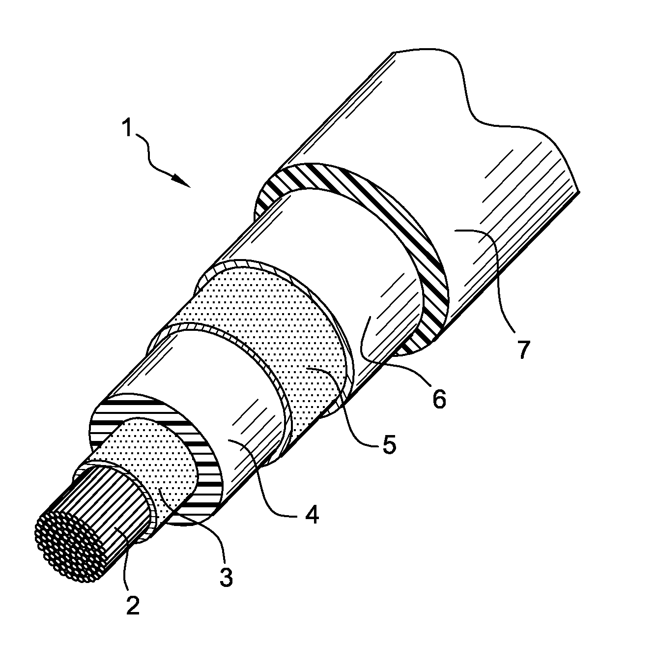
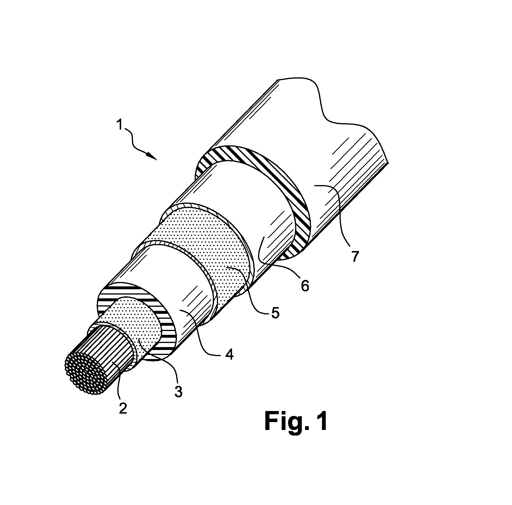
[0070]The electric cable of the present invention can include an elongated central conducting element, especially made of copper or aluminum, surrounded by an extruded semiconducting layer, said extruded semiconducting layer being surrounded by an extruded electrically insulating layer, so that a 2-layer insulation is obtained.

[0071]The semiconducting layer can be made from a silicone rubber composition commercialized by the company RADO under the reference Silopren 2270H, wherein carbons rovings have been mixed. The mixture can be done with a roll or a mixer. Said silicone rubber composition mixed with carbon rovings is then extruded in using an extruder, around the elongated central conducting element.

[0072]In a first example (example 1), said carbon rovings have a length 200 μm and are commercialized by the compan...


PUM


Abstract

An electric cable made from at least one elongated electric conductor and a multilayer insulation surrounding the electric conductor. The multilayer insulation has a first semiconducting layer and an electrically insulating layer, where the two layers are made from a silicone rubber based composition. The semiconducting silicone rubber based composition of the first semiconducting layer has carbon rovings as conductive filler.

Description

RELATED APPLICATION[0001]This application claims the benefit of priority from European Patent Application No. 12 306 160.8, filed on Sep. 25, 2012, the entirety of which is incorporated by reference.BACKGROUND[0002]1. Field of the Invention[0003]The present invention relates to an electric cable including a multilayer insulation made from silicone rubber, as well as a manufacturing process of said electric cable.[0004]More particularly, it applies typically, but not exclusively, to the fields of power cables, such as medium voltage (especially from 5 kV to 45-60 kV) or high voltage (especially greater than 60 kV, which may be up to 800 kV) power cables, whether they are direct voltage (DC) or alternative voltage (AC) cables.[0005]2. Description of Related Art[0006]Medium voltage or high voltage power cables typically comprise a central electric conductor and, successively and coaxially around this electric conductor, a semiconducting inner layer, an electrically insulating (intermed...

Claims


Application Information

Patent Timeline
IPC IPC(8): H01B7/02
CPCH01B7/0225H01B1/24H01B3/46H01B9/027H01B9/00
Inventor JEKER, THOMASHANER, FRANZGASSER, MARKUS
Owner NEXANS
Why Eureka
Try Eureka