Magnetic field sensor system with a biasing magnet producing a spatially symmetric magnetic field within a plane being defined by magnetoresistive sensor elements

a sensor element and biasing magnet technology, applied in the field of magnetic field sensors, can solve the problems of reducing the efficiency reducing the accuracy so as to achieve the optimization of the magnetic field sensor system performance, the effect of avoiding unwanted saturation of the magnetoresistive sensor elements and excellent sensitivity

Active Publication Date: 2014-03-27
NXP BV
View PDF1 Cites 32 Cited by
  • Summary
  • Abstract
  • Description
  • Claims
  • Application Information

AI Technical Summary

Benefits of technology

[0036]The magneetoresisitve sensor elements may be arranged directly at the biasing magnet while maintaining the symmetry of the biasing magnetic field, wherein an y-component of the biasing magnetic field is symmetric with respect to the y=0 plane. This may allow for realizing the described magnetic field sensor system within a small or compact design while maintaining the excellent sensitivity because the biasing magnetic field of the comparatively strong biasing magnet is parallel to the easy axes directions of the magnetoresistive sensor elements. As a consequence, an unwanted saturation of the magnetoresistive sensor elements can be easily avoided.
[0037]The spatial dimensions of the biasing magnet may be much larger than the spatial dimension of the magnetoresistive sensor arrangement respectively of the semiconductor die carrying the magnetoresistive sensor elements. Therefore, since the semiconductor die is placed in the centre of the magnet's face, the direction of the easy ax

Problems solved by technology

Hall sensors and MTs, which rely on the Lorentz force, have a comparatively low sensitivity and consequently also a low accuracy.
AMR sensors, while having a much higher sensitivity compared to Hall effect sensors and MTs, require more fabrication steps because they cannot easily be integrated monolithically, making a total sensor system ore expensive.
The technology required to fabricate such sensors in considerably more complicated and expensive.
Furthermore, due to the thin multiple layers making up a GMR sens

Method used


Image

  • Magnetic field sensor system with a biasing magnet producing a spatially symmetric magnetic field within a plane being defined by magnetoresistive  sensor elements
  • Magnetic field sensor system with a biasing magnet producing a spatially symmetric magnetic field within a plane being defined by magnetoresistive  sensor elements
  • Magnetic field sensor system with a biasing magnet producing a spatially symmetric magnetic field within a plane being defined by magnetoresistive  sensor elements

Examples


Embodiment Construction

[0050]The illustration in the drawing is schematically. It is noted that in different figures, similar or identical elements of features are provided with the same reference signs or with reference signs, which are different from the corresponding reference signs only within the first digit. In order to avoid unnecessary repetitions elements or features which have already been elucidated with respect to a previously described embodiment are not elucidated again at a later position of the description.

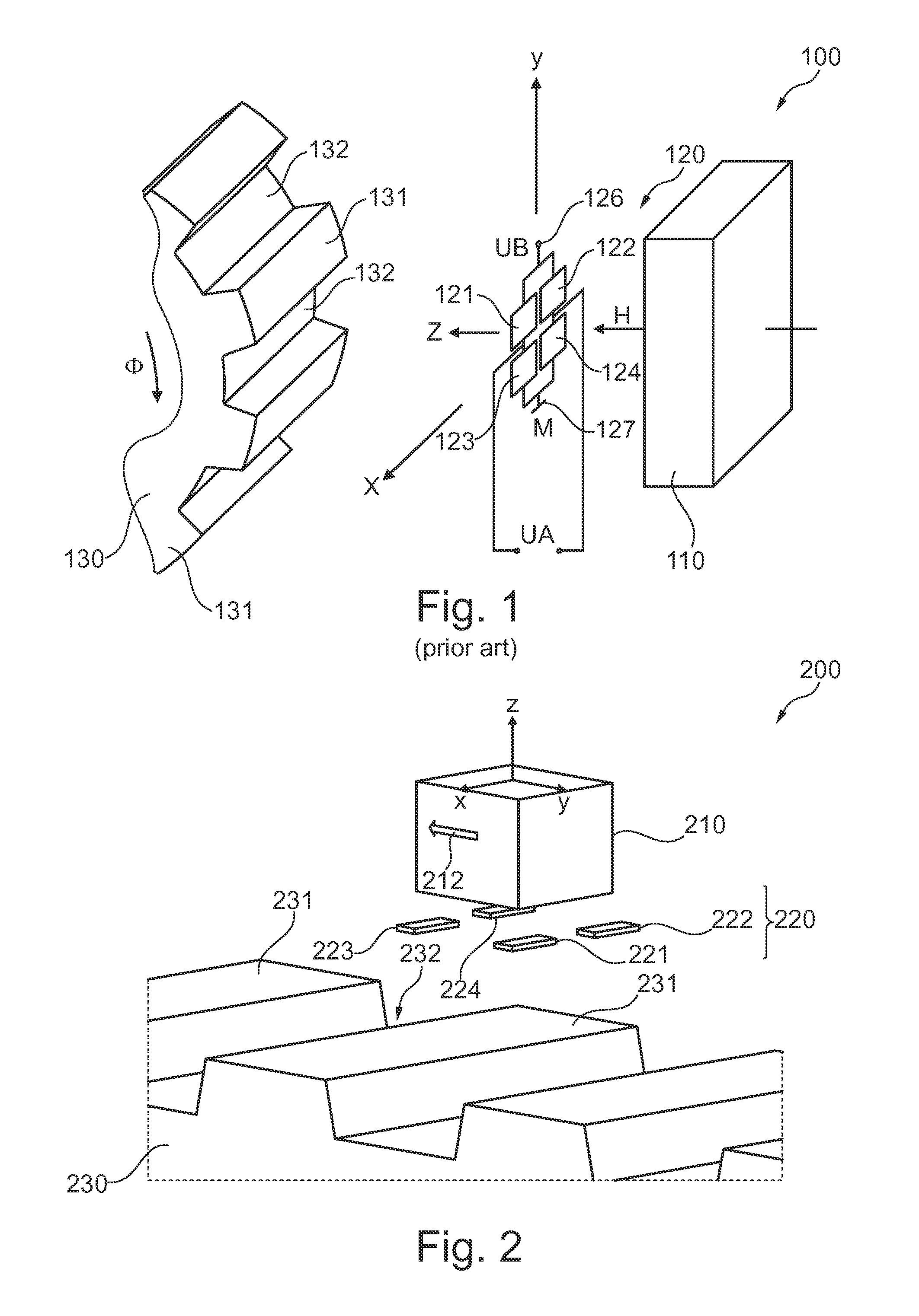
[0051]FIG. 1 shows a known magnetic field sensor system 100 for illustrating the basic physical principles of sensing a rotational movement by means of a magnetoresistive sensor arrangement 120 comprising four magnetoresistive sensor elements 121, 122, 123 and 124. As can be seen from FIG. 1, the magnetic field sensor system 100 comprises a biasing magnet 110 producing a biasing magnetic field H, the already mentioned magnetoresistive sensor arrangement 120 and an encoded soft magnetic w...


PUM


Abstract

A magnetic field sensor system for measuring rotational movements of a shaft is disclosed. The sensor system includes a biasing magnet configured for generating a biasing magnetic field and a magnetic wheel having a wheel axis and a circumferential surface which comprises a regular structure of teeth and gaps arranged in an alternating manner. The magnetic wheel is attachable to the shaft and is magnetizable by the biasing magnetic field. A magnetoresistive sensor arrangement comprising four magnetoresistive sensor elements being connected with each other in a Wheatstone bridge, respectively two of the magnetoresistive sensor elements being assigned to one half bridge of the Wheatstone bridge. The four magnetoresistive sensor elements are arranged within an x-y plane.

Description

FIELD OF THE INVENTION [0001]The present invention generally relates to the technical field of magnetic field sensors. In particular, the present invention relates to a magnetic field sensor system comprising a biasing magnet, and encoded soft magnetic wheel having a teeth structure and magnetoresistive sensor elements, which with the help of an appropriate evaluation electronic are capable of determining positional information of the encoded soft-magnetic element.BACKGROUND OF THE INVENTION [0002]Magnetic sensors are increasingly important in various industries. For instance in the automotive industry various sensors such as parking sensors, angular sensors e.g. in throttle valves, ABS (Automatic Braking System) sensors and tire pressure sensors can be found in modern vehicles for improving comfort and safety. Magnetic sensors are particularly important in automotive applications, because magnetic fields penetrate easily through most materials. Magnetic sensors are also highly inse...

Claims


Application Information

Patent Timeline
IPC IPC(8): G01B7/30
CPCG01B7/30G01R33/0011G01R33/091G01D5/147G01D5/145
Inventor RUIGROK, JAAP JOSEPHUS MARIANAZARIAN, ALEXE LEVANVANHELMONT, FREDERIK WILLEM MAURITS
Owner NXP BV
Why Eureka
Try Eureka