Technique for tomographic image recording
a technology of tomographic image and recording, which is applied in the field of tomographic image recording apparatus, can solve the problems of destroying specimens, changing specimens in uncontrolled manners, and reducing radiation intensity with comparable image results, and achieves the effect of larger numerical aperture and higher resolution
- Summary
- Abstract
- Description
- Claims
- Application Information
AI Technical Summary
Benefits of technology
Problems solved by technology
Method used
Image

Examples
third embodiment
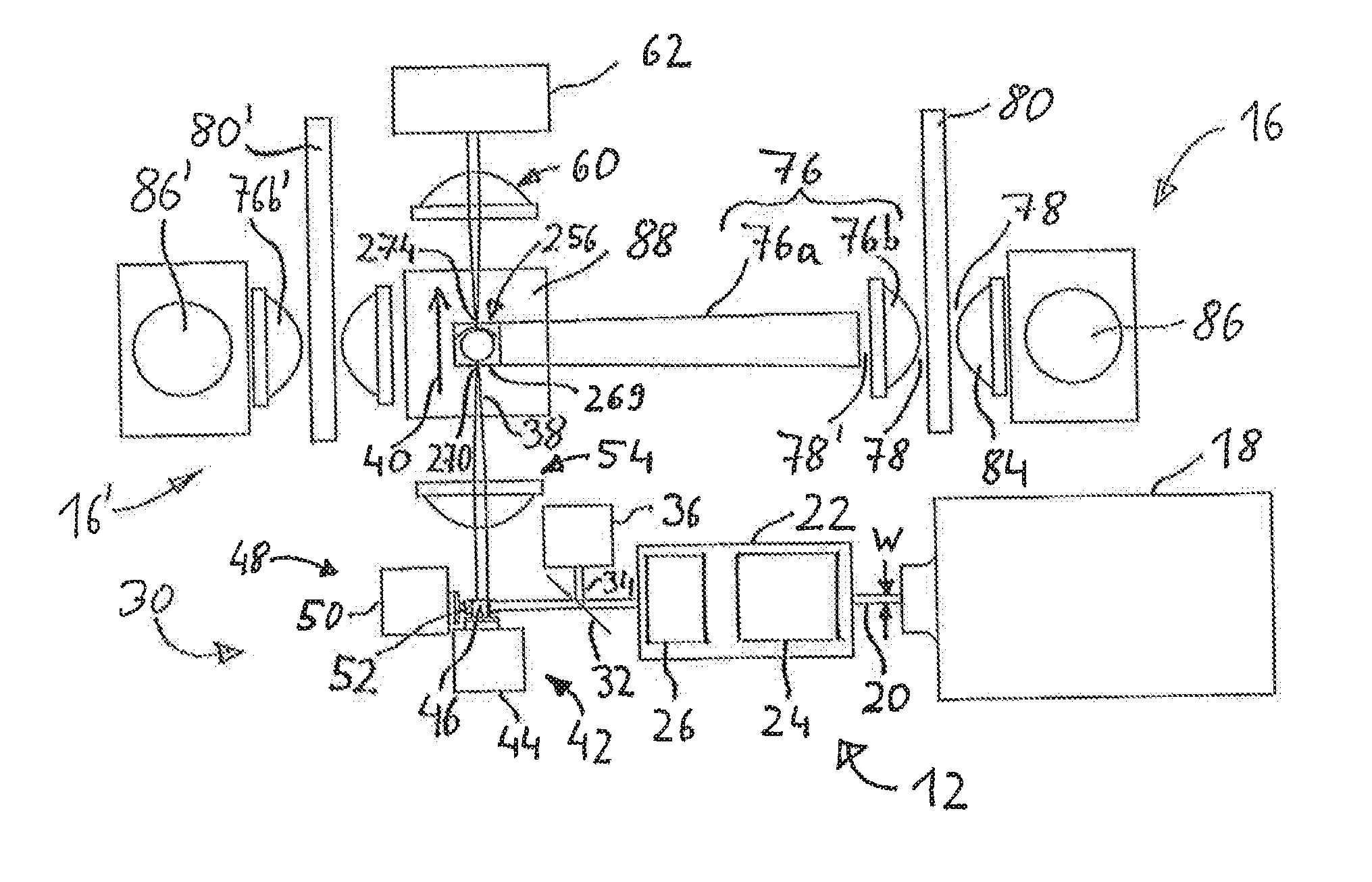
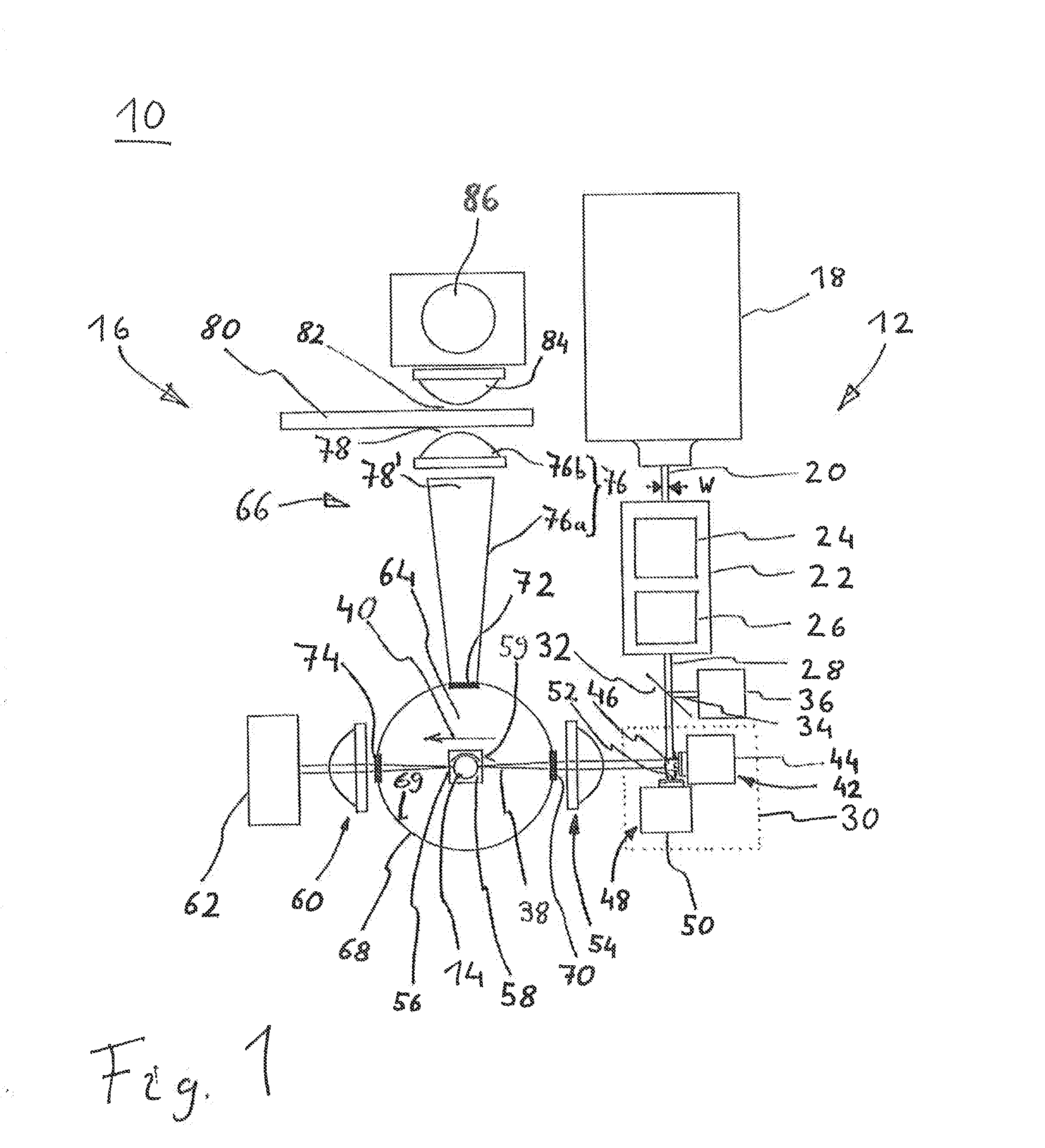
[0068]The specimen holder 14 has been rotatably arranged in a specimen vessel 56, preferentially a cell. A liquid (which in the case of the specimen vessel 14 coincides, at least with regard to its refractive index, with the aforementioned liquid) adapted to the specimen as regards its refractive index is located between the specimen holder 14 and the specimen vessel 56. The rotation relates to a relative rotation between, on the one hand, the specimen holder 14 and, on the other hand, at least the light-source 12 and the specimen vessel 56. In principle, a “boundary” or “interface” of the rotation extends between the specimen holder 14 and the specimen vessel 56 (particularly since the specimen vessel 56 may exhibit entrance windows and exit windows, described below, for the pencil beam 38, the location of which, with a view to simplified reconstruction, should not be rotated in relation to the pencil beam 38). An axis of rotation of the rotation is vertical (perpendicular to the p...
fourth embodiment
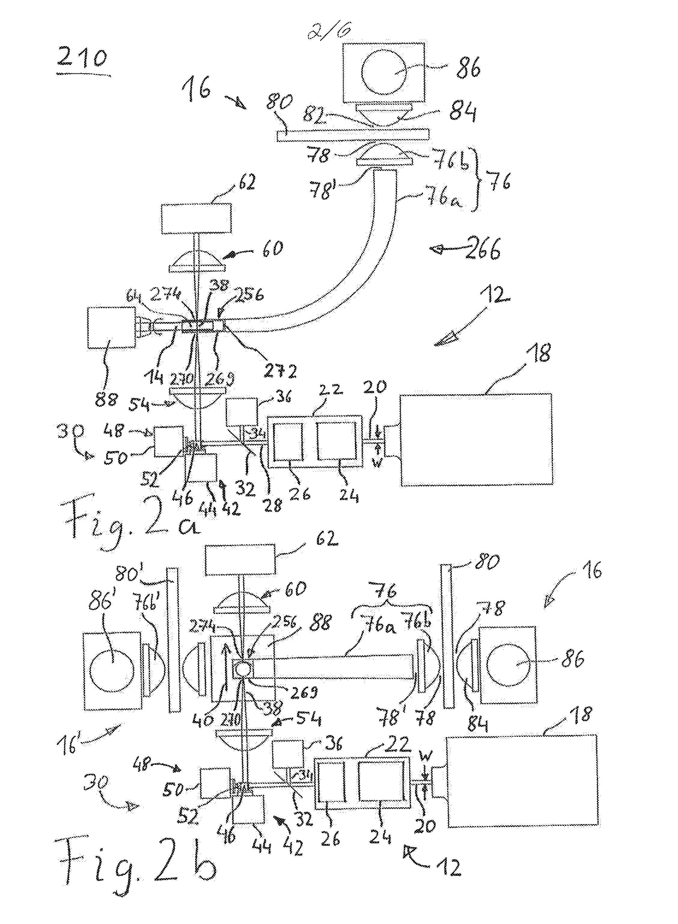
[0108]With a view to radiating the pencil beam 38, and optionally for transmission detection, the specimen vessel 256 exhibits an illumination aperture 270 and a transmission aperture 274, respectively. The illumination aperture 270 and, where appropriate, the transmission aperture 274 correspond (functionally) to aperture 70 and to aperture 74, respectively. As described above in connection with apertures 70, 72, 74, with a view to minimising radiation losses apertures 270 and 274 take the form of narrow slits in the x-direction, and the optical control element 30 rasterises the pencil beam 38 only in the x-direction. For measuring positions with y-offset, the specimen holder 14 can be moved relative to all other components in the y-direction, whereby the specimen holder 14 or the other components are stationary, as has been described above for the first exemplary embodiment. The reflecting surface 269 exhibits opposing beam-transparent slits by way of apertures 270 and 274. In the...
fifth embodiment
[0110]the specimen vessel 256 shown in FIG. 2 for fluorescent radiation by way of scattered radiation includes a transparent base body which exhibits a dichroic layer on the side surfaces. Alternatively or in supplement, the side surfaces of the specimen vessel consist of a dichroic filter or an interference filter. In this way, the side surfaces of the specimen vessel 256 have been designed to transmit the exciting radiation (of the pencil beam 38) and to reflect the fluorescent radiation. In this way, a proportion of the scattered radiation 64 of about 50% or more can be acquired. With regard to the fluorescent radiation (i.e. the scattered radiation 64), the side faces act as reflecting surface 269. Since the side faces are transparent with regard to the exciting radiation (of the pencil beam 38), the side surfaces in addition enable the entrance and exit of the pencil beam 38. That is to say, the entire side surfaces are available by way of illumination aperture 270 or transmiss...
PUM
 Abstract
Description
Claims
Application Information
 - R&D
- Intellectual Property
- Life Sciences
- Materials
- Tech Scout
- Unparalleled Data Quality
- Higher Quality Content
- 60% Fewer Hallucinations
Browse by: Latest US Patents, China's latest patents, Technical Efficacy Thesaurus, Application Domain, Technology Topic, Popular Technical Reports.
© 2025 PatSnap. All rights reserved.Legal|Privacy policy|Modern Slavery Act Transparency Statement|Sitemap|About US| Contact US: help@patsnap.com