Receiving circuit and signal receiving method

Inactive Publication Date: 2014-03-27
RENESAS ELECTRONICS CORP
View PDF5 Cites 24 Cited by
  • Summary
  • Abstract
  • Description
  • Claims
  • Application Information

AI Technical Summary

Benefits of technology

[0029]According to the present invention, it is possible to provide a receiving circuit and a signal receiving method that c

Problems solved by technology

When transmitting a signal between a plurality of semiconductor chips with different power supply voltages, if the signal is transmitted directly through a wire, it can

Method used


Image

  • Receiving circuit and signal receiving method
  • Receiving circuit and signal receiving method
  • Receiving circuit and signal receiving method

Examples


first embodiment

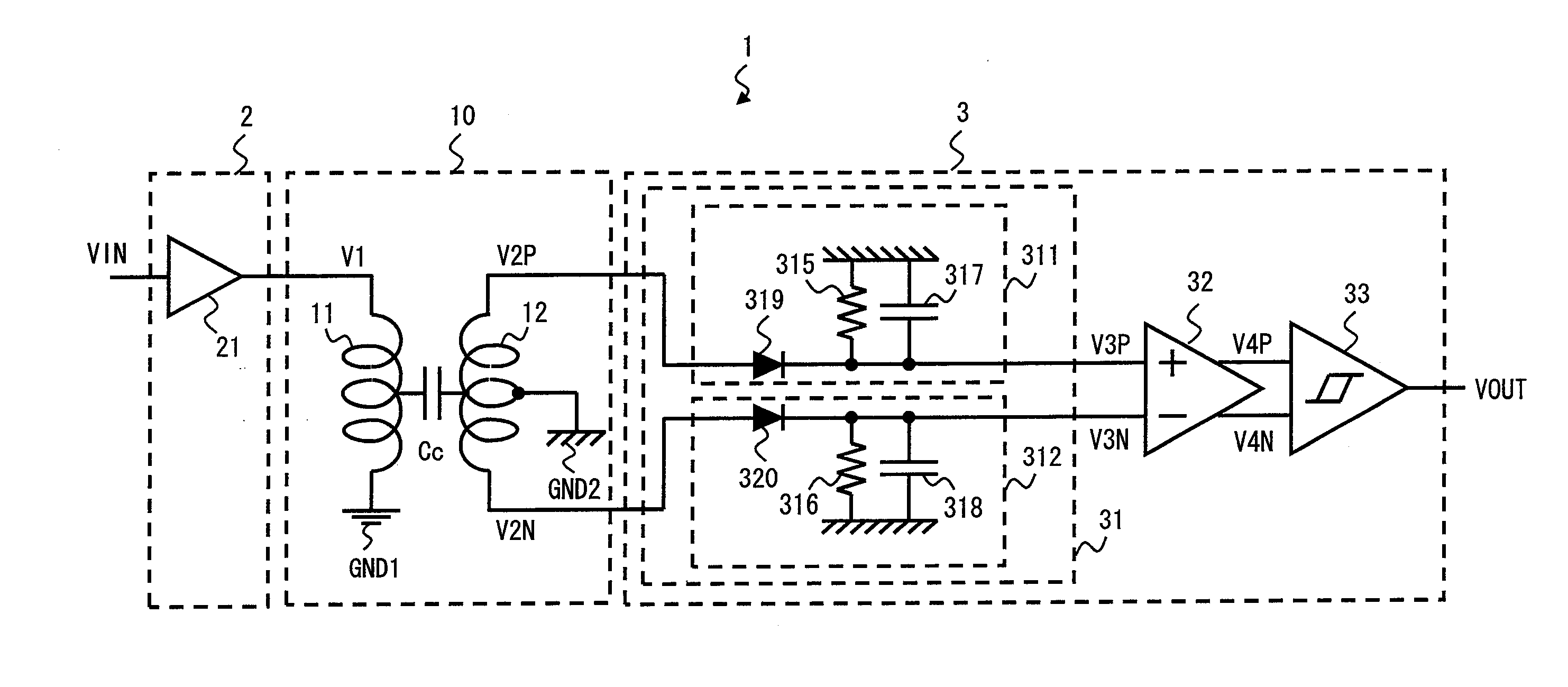
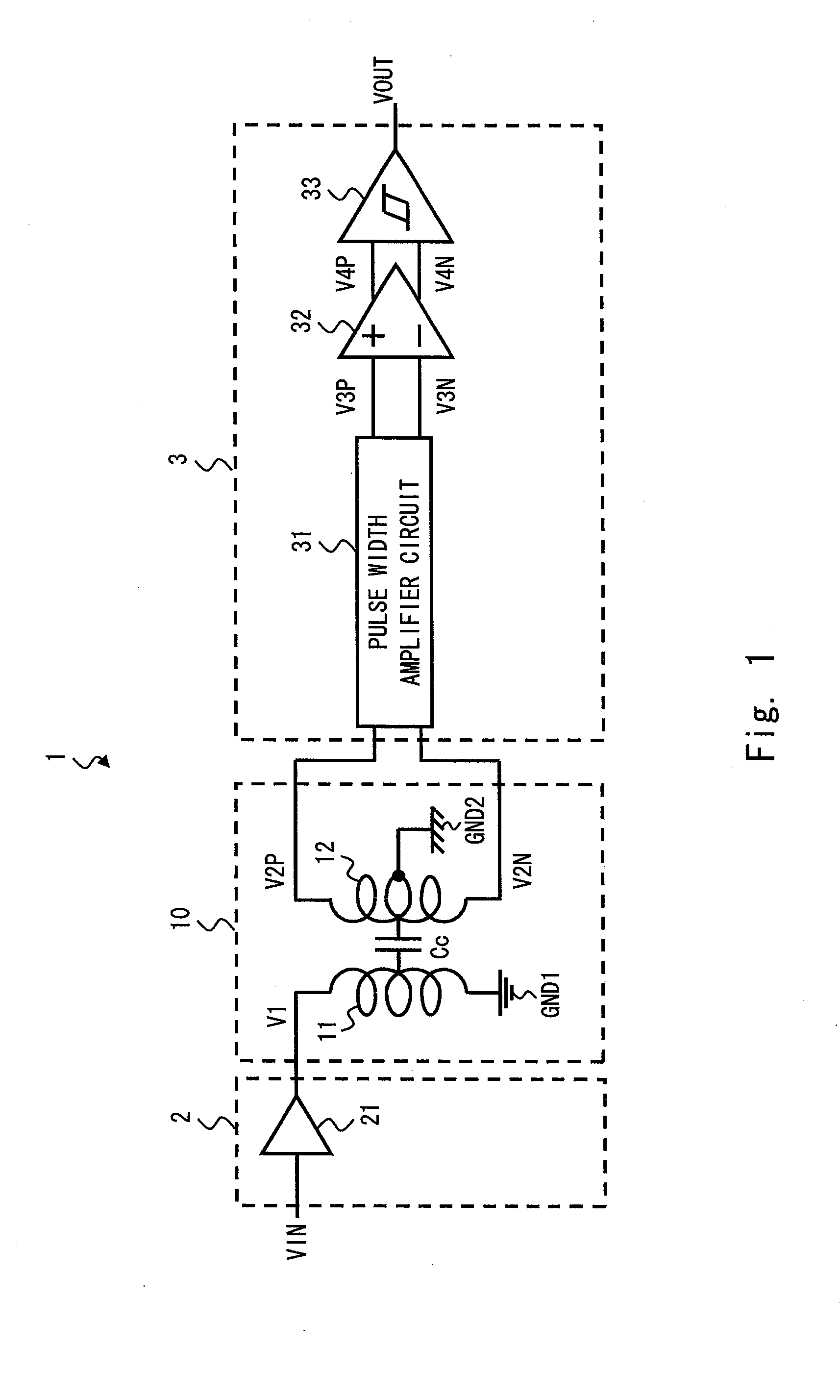
[0087]FIG. 1 is a diagram showing a signal transmission system 1 according to a first embodiment of the invention. A receiving circuit 3 in the signal transmission system 1 according to this embodiment includes a pulse width amplifier circuit that increases the pulse width of pulse signals appearing at both ends of a secondary coil 12 having a center tap and outputs them as first and second hold signals. Note that a specified voltage is supplied from an external terminal to the center tap of the secondary coil. The receiving circuit 3 can thereby suppress the effect of the common mode voltage and prevent signal transmission error without increase in circuit size. This is specifically described hereinbelow.

[0088]The signal transmission system 1 shown in FIG. 1 includes a transmitting circuit 2, a receiving circuit 3, and a transformer 10. The transformer 10 includes a primary coil 11 and a secondary coil 12. The transformer 10 is an AC coupling device that transmits an AC signal from...

second embodiment

[0128]FIG. 7 is a diagram showing a signal transmission system 1a according to a second embodiment of the invention. The signal transmission system 1a according to this embodiment is different from the signal transmission system 1 according to the first embodiment shown in FIG. 5 in that it further includes protection diodes 35 and 36. The other circuit structure of the signal transmission system 1a according to this embodiment is the same as that of the signal transmission system 1 according to the first embodiment shown in FIG. 5 and thus not redundantly described.

[0129]The anode of the protection diode 35 is connected to the ground voltage terminal GND2, and the cathode of the protection diode 35 is connected to one end of the secondary coil 12. The anode of the protection diode 36 is connected to the ground voltage terminal GND2, and the cathode of the protection diode 36 is connected to the other end of the secondary coil 12.

[0130]When the voltage of the received signal V2P fal...

third embodiment

[0132]FIG. 8 is a diagram showing a signal transmission system 1b according to a third embodiment of the invention. The signal transmission system 1b according to this embodiment is different from the signal transmission system 1a according to the second embodiment in the structure of the pulse width amplifier circuit 31. The other circuit structure of the signal transmission system 1b according to this embodiment is the same as that of the signal transmission system 1a according to the second embodiment and thus not redundantly described.

[0133]The pulse width amplifier circuit 31 shown in FIG. 8 includes diodes 319 and 320, resistor elements 315 and 316, and a capacitor element (third capacitor element) 321. The anode of the diode 319 is connected to one end of the secondary coil 12, and the cathode of the diode 319 is connected to the non-inverting input terminal of the differential amplifier 32. In the resistor element 315, one end is connected to the non-inverting input terminal...


PUM


Abstract

Provided is a receiving circuit that operates in a power supply system different from a transmitting circuit outputting a transmission signal and receives the transmission signal through an AC coupling device where a primary coil through which the transmission signal flows and a secondary coil having a center tap to which a specified voltage is supplied from an external terminal are magnetically coupled, which includes a pulse width amplifier circuit that holds pulse signals appearing at both ends of the secondary coil for a specified period of time and outputs them as hold signals, respectively, and a differential amplifier that compares a voltage of the hold signal and a voltage of the hold signal and outputs a comparison result.

Description

TECHNICAL FIELD[0001]The present invention relates to a receiving circuit and a signal receiving method and, particularly, to a receiving circuit and a signal receiving method that receive a signal through an AC coupling device.BACKGROUND ART[0002]When transmitting a signal between a plurality of semiconductor chips with different power supply voltages, if the signal is transmitted directly through a wire, it can cause damage to the semiconductor chips or a problem in signal transmission due to a voltage difference generated in the DC voltage component of the transmitted signal. Thus, when transmitting a signal between a plurality of semiconductor chips with different power supply voltages, the semiconductor chips are connected via an AC coupling device, so that only an AC signal is transmitted. As the AC coupling device, a capacitor or a transformer can be used.[0003]The transformer is an AC coupling device where a primary coil and a secondary coil are magnetically coupled. In the ...

Claims


Application Information

Patent Timeline
IPC IPC(8): H02M7/06
CPCH02M7/06H04B3/50H01L2224/48137H04L25/4902H01L2924/13091H01L2224/451H01L2924/12032H04B5/0031H01L2924/00H01L2924/00014H04L25/0266
Inventor KAERIYAMA, SHUNICHIYAMAGUCHI, KOUICHINOSE, KOICHI
Owner RENESAS ELECTRONICS CORP
Why Eureka
Try Eureka