Pressure regulator, polishing apparatus having the pressure regulator, and polishing method

Active Publication Date: 2014-03-27
EBARA CORP
View PDF0 Cites 20 Cited by
  • Summary
  • Abstract
  • Description
  • Claims
  • Application Information

AI Technical Summary

Benefits of technology

[0017]Another aspect of the present invention provides a polishing apparatus, comprising: a polishing table for supporting a polishing pad; a top ring configured to press a substrate against the polishing pad, the top ring having a pressure chamber for pressing the substrate against the polishing pad; and a pressure regulator coupled to the top ring and configured to regulate pressure in the pressure chamber, the pressure regulator including: a pressure-regulating valve configured to regulate pressure of a fluid supplied from a fluid supply source; a first pressure sensor configured to measure the pressure regulated by the pressure-regulating valve; a second pressure sensor located downstream of the first pressure sensor; a PID controller configured to produce a correction pressure command value for eliminating a difference between a pressure command value and a pressure value of the fluid measured by the second pressure sensor; and a regulator controller configured to control operation of the pressure-regulating valve so as to eliminate a difference between the correction pressure command value and a pressure value of the fluid measured by the first pressure sensor.
[0018]Still another aspect of the present invention provides a polishing method, comprising: supplying a fluid from a fluid supply source into a pressure chamber of a to

Problems solved by technology

Moreover, if the polishing pressure on the wafer is controlled based on the pressure t

Method used


Image

  • Pressure regulator, polishing apparatus having the pressure regulator, and polishing method
  • Pressure regulator, polishing apparatus having the pressure regulator, and polishing method
  • Pressure regulator, polishing apparatus having the pressure regulator, and polishing method

Examples


Embodiment Construction

[0035]Embodiments of the present invention will be described below with reference to the drawings.

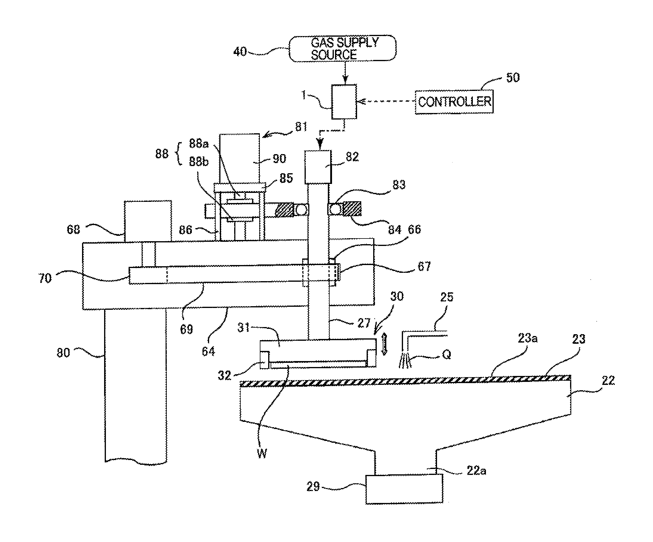
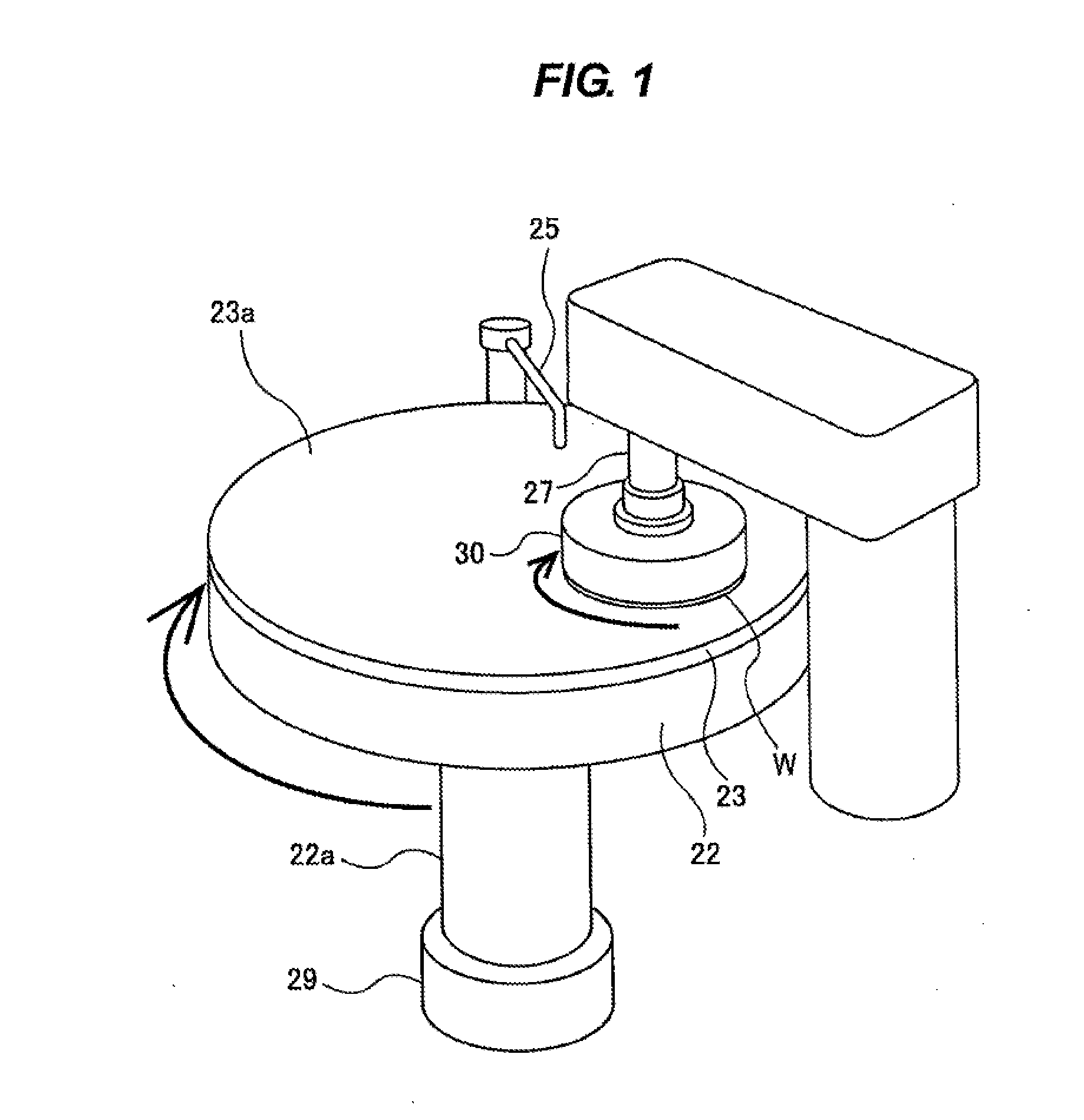
[0036]FIG. 3 is a schematic view showing a polishing apparatus including a pressure regulator according to an embodiment. As shown in FIG. 3, the polishing apparatus includes a polishing table 22 supporting a polishing pad 23, and a top ring (or a substrate holder) 30 for holding a substrate, such as a wafer, as an object to be polished and pressing the substrate against the polishing pad 23 on the polishing table 22.

[0037]The polishing table 22 is coupled via a table shaft 22a to a table motor 29 which is disposed below the polishing table 22, and the polishing table 22 is rotatable about the table shaft 22a. The polishing pad 23 is attached to an upper surface of the polishing table 22. The polishing pad 23 has a surface 23a that serves as a polishing surface for polishing a wafer W. A polishing liquid supply unit 25 is provided above the polishing table 22 to supply a polishing liqui...


PUM

PropertyMeasurementUnit
Temperatureaaaaaaaaaa
Pressureaaaaaaaaaa
Stabilityaaaaaaaaaa

Abstract

A pressure regulator includes: a pressure-regulating valve configured to regulate pressure of a fluid supplied from a fluid supply source; a first pressure sensor configured to measure the pressure regulated by the pressure-regulating valve; a second pressure sensor located downstream of the first pressure sensor; a PID controller configured to produce a correction pressure command value for eliminating a difference between a pressure command value and a pressure value of the fluid measured by the second pressure sensor; and a regulator controller configured to control operation of the pressure-regulating valve so as to eliminate a difference between the correction pressure command value and a pressure value of the fluid measured by the first pressure sensor.

Description

CROSS-REFERENCE TO RELATED APPLICATIONS[0001]This application claims priority to Japanese Patent Application No. 2012-162248 filed Jul. 23, 2012, the entire contents of which are hereby incorporated by reference.BACKGROUND OF THE INVENTION[0002]1. Field of the Invention[0003]The present invention relates to a pressure regulator for regulating pressure in a pressure chamber used for pressing a substrate, such as a wafer, against a polishing pad. The present invention further relates to a polishing apparatus having such a pressure regulator. The present invention further relates to a polishing method using the aforementioned polishing apparatus.[0004]2. Description of the Related Art[0005]FIG. 1 is a schematic view of a polishing apparatus for polishing a wafer. As shown in FIG. 1, the polishing apparatus has a polishing table 22 for supporting a polishing pad 23, and a top ring 30 for pressing a wafer W against the polishing pad 23. The polishing table 22 is coupled to a table motor ...

Claims


Application Information

Patent Timeline
IPC IPC(8): B24B37/34B24B37/005
CPCB24B37/005B24B37/345B24B7/228Y10T137/7761B24B7/22B24B37/34B24B49/00G05D16/20H01L21/304
Inventor TAKAHASHI, NOBUYUKIMARUYAMA, TORU
Owner EBARA CORP
Why Eureka
Try Eureka