Scc equipped with foam removal unit

a technology of foam removal unit and spinning cone, which is applied in the direction of foam dispersion/prevention, transportation and packaging, rotary stirring mixer, etc., can solve the problems of increasing the cost of a reactor, short disc residence time of raw materials, and reducing the stability of reactants, so as to improve the removal yield and product stability, reduce the cost, and improve the effect of removal yield

Active Publication Date: 2014-03-27
LG CHEM LTD
View PDF1 Cites 4 Cited by
  • Summary
  • Abstract
  • Description
  • Claims
  • Application Information

AI Technical Summary

Benefits of technology

[0025]The SCC according to the present invention solves the problems that foam is generated when separating material to be removed to decrease removal yield and lower stability of the product, and may improve removal yield and product stability because a foam removal unit for removing generated foam is installed. And, to solve the problem that foam removal efficiency is lowered if foam removal is conducted only at the upper part of SCC, a collection tube connecting the foam removal unit and the inside of the housing is connected per flow path of each stage to remove foam at each stage, thus increasing foam removal efficiency and improving operability of SCC.

Problems solved by technology

However, according to this method, sufficient reactions are not achieved for a reaction requiring rapid material transfer speed, thus generating a large amount of non-raw product, and if a catalyst is used, a catalyst separation process is required thus increasing a cost as a reactor has large-capacity.
Therefore, Korean Registered Patent No. 961,765 has suggested a spinning disc reactor, but it has a problem in that disc residence time of raw material is short because spinning discs are horizontally arranged, and thus, a spinning cone column (SCC) with improved residence time of raw materials by multistage installation of inclined discs, namely cones has been preferred.
In case the SCC is applied for a gas-liquid contacting separation process, foam may be generated to lower stability of reactant and decrease yield in the process of removing material to be removed by contacting, and thus, there is a need to remove the foam.

Method used


Image

  • Scc equipped with foam removal unit
  • Scc equipped with foam removal unit
  • Scc equipped with foam removal unit

Examples


Embodiment Construction

[0026]The present invention may have many examples and various modifications may be made, and specific examples will be illustrated in drawings and explained in detail. However, it should be understood that the present invention is not limited to specific examples, and includes all modifications, equivalents or substitutions within the scope and technical scope of the invention. In the explanations of the invention, detailed explanations of related known technologies may be omitted if it is judged to obscure the subject matter of the invention.

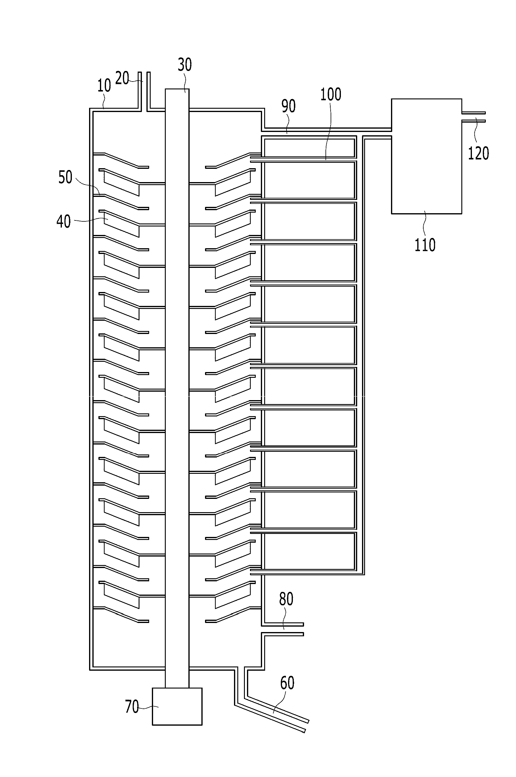
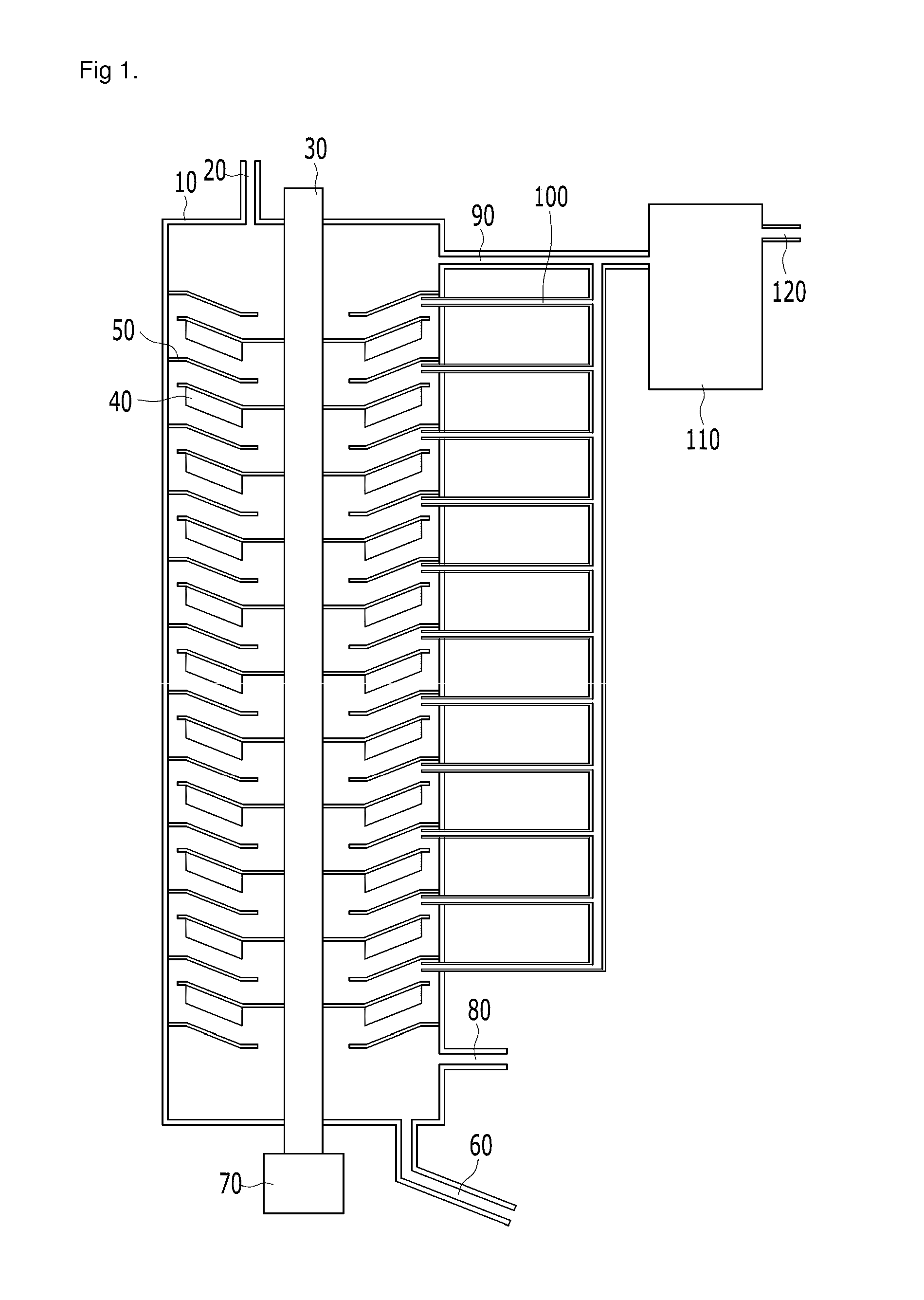
[0027]The present invention provides a SCC comprising: a housing (10) having a rotation axis (30); a supply part (20) of at least one reactant formed inside of the housing; at least two spinning cones (40) that are installed so as to have a constant gradient to the rotation axis from the upper part to the lower part, move reactants supplied through the reactant supply part, and rotate around the rotation axis (30); a fixed cone (50) that is fi...


PUM

PropertyMeasurementUnit
rotation speedaaaaaaaaaa
temperatureaaaaaaaaaa
volatileaaaaaaaaaa

Abstract

The present invention provides a SCC (Spinning Cone Column) equipped with a foam removal unit comprising: a housing having a rotation axis; a supply part of at least one reactant formed inside of the housing; at least two spinning cones that are installed so as to have a constant gradient from the upper part to the lower part to the rotation axis, move supplied reactants through the reactant supply part, and rotate around the rotation axis; a fixed cone that is fixed and formed on the inner side of the housing, and provides a pathway for sequentially moving reactant from a spinning cone at the upper part to a spinning cone at the lower part; a product collection part for collecting reactants moved through the spinning cone and the fixed cone; and a driving part for rotating the spinning cone, wherein a foam removal unit is installed on one side of the housing. The SCC according to the present invention solves the problems that foam is generated when separating material to be removed to decrease removal yield and lower stability of the product, and may improve removal yield and product stability because a foam removal unit is for removing generated foam is installed.

Description

BACKGROUND OF THE INVENTION[0001](a) Field of the Invention[0002]The present invention relates to a SCC (spinning cone column) equipped with a foam removal unit, more particularly to a SCC equipped with a foam removal unit for removing foam generated in the SCC.[0003](b) Description of the Related Art[0004]In general, to obtain a product through a chemical reaction, a reaction device is required. As the reaction device, a batch reactor where raw product is added to one reactor, and then, a reaction is conducted through agitation, and the like has been generally used. However, according to this method, sufficient reactions are not achieved for a reaction requiring rapid material transfer speed, thus generating a large amount of non-raw product, and if a catalyst is used, a catalyst separation process is required thus increasing a cost as a reactor has large-capacity.[0005]Therefore, Korean Registered Patent No. 961,765 has suggested a spinning disc reactor, but it has a problem in th...

Claims


Application Information

Patent Timeline
Patent Type & Authority Applications(United States)
IPC IPC(8): B01J19/28C08F2/01B01F27/93
CPCC08F2/01B01J19/28B01D19/02B01J19/006B01J19/0066B01J2219/0077B01J2219/00777B01J2219/00779B01J19/18C08J11/02B01F27/93
Inventor JOO, EUN-JUNGLEE, DONG-KWONSHIN, DAE-YOUNGLEE, JONG-KU
Owner LG CHEM LTD
Why Eureka
Try Eureka