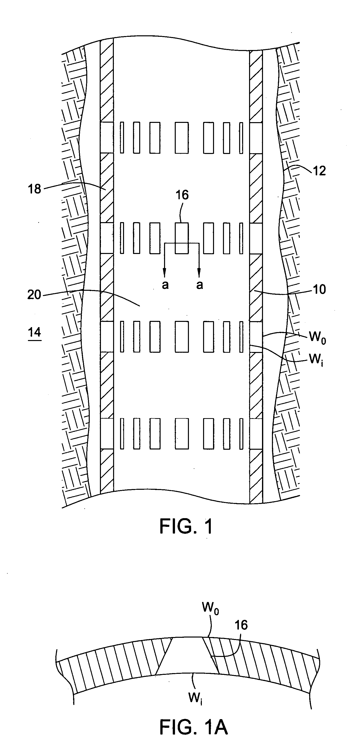
[0014] The form of openings present in the walls of tubular members in accordance with these embodiments of the present invention is of course unlike the form of openings that would be achieved if a normally apertured planar sheet, in which openings have parallel walls, is rolled into a tubular form, which tends to create openings in which the inner width of the openings is less than the outer width. Furthermore, conventional slotted liner, made of oilfield
pipe that has been longitudinally slotted with a precision saw or mill, will feature parallel side walls and will tend to have an outer length greater than an inner length. Thus this aspect of the invention provides the preferred form of openings for sand exclusion such as is achieved in wire-wrapped screens, but without the complexity and expense associated with wire-wrapped screens, and in a relatively robust form.
[0021] Existing tubular members are slotted to create filters using a precision saw or mill. The use of a precision
cutting tool is necessary to provide the accurately controlled slot width required to provide an effective filter with predictable sand control properties. However, the applicant has now achieved the previously unattainable accuracy required of filter slots or openings by
laser-
cutting. Conventionally, a slot
cut by
laser has a larger width at the slot ends, where
cutting commenced and stopped, producing “dog-bone” slots, which are of little if any utility in filter applications. A conventional
laser cutting operation utilises a substantially constant laser energy input, and when cutting commences the laser is held stationary relative to the workpiece until the laser has
cut through the depth of the
metal, before moving along the workpiece to
cut the slot, and then coming to a stop at the end of the slot. Applicant believes that, without wishing to be bound by theory, where the laser is held stationary relative to the workpiece,
energy transfer to the workpiece from the laser creates a
pool of
molten metal surrounding the area of
metal which is removed by vaporisation, and this
pool of
molten metal is removed from the workpiece with the vaporised
metal. This has the effect that the width of cut is increased relative to areas where the laser is moving relative to the workpiece, and where less metal is removed by this mechanism. The applicant has found that it is possible to avoid this problem by controlling the laser energy during the cutting process, and more particularly by reducing the laser energy when the laser is stationary relative to the workpiece. By doing so it has been possible to cut slots of consistent width, suitable for use in filtering applications. Other techniques may be utilised to control slot width, including reducing the flow rate of purging gas, and thus reducing the rate of removal of
molten metal. Alternatively, or additionally, a
pulsed laser may be used, which laser produces discrete energy pulses such that, in use, a laser spot is not focussed on the workpiece for a time which is sufficient to allow
thermal energy to be conducted into the metal surrounding the cutting zone.
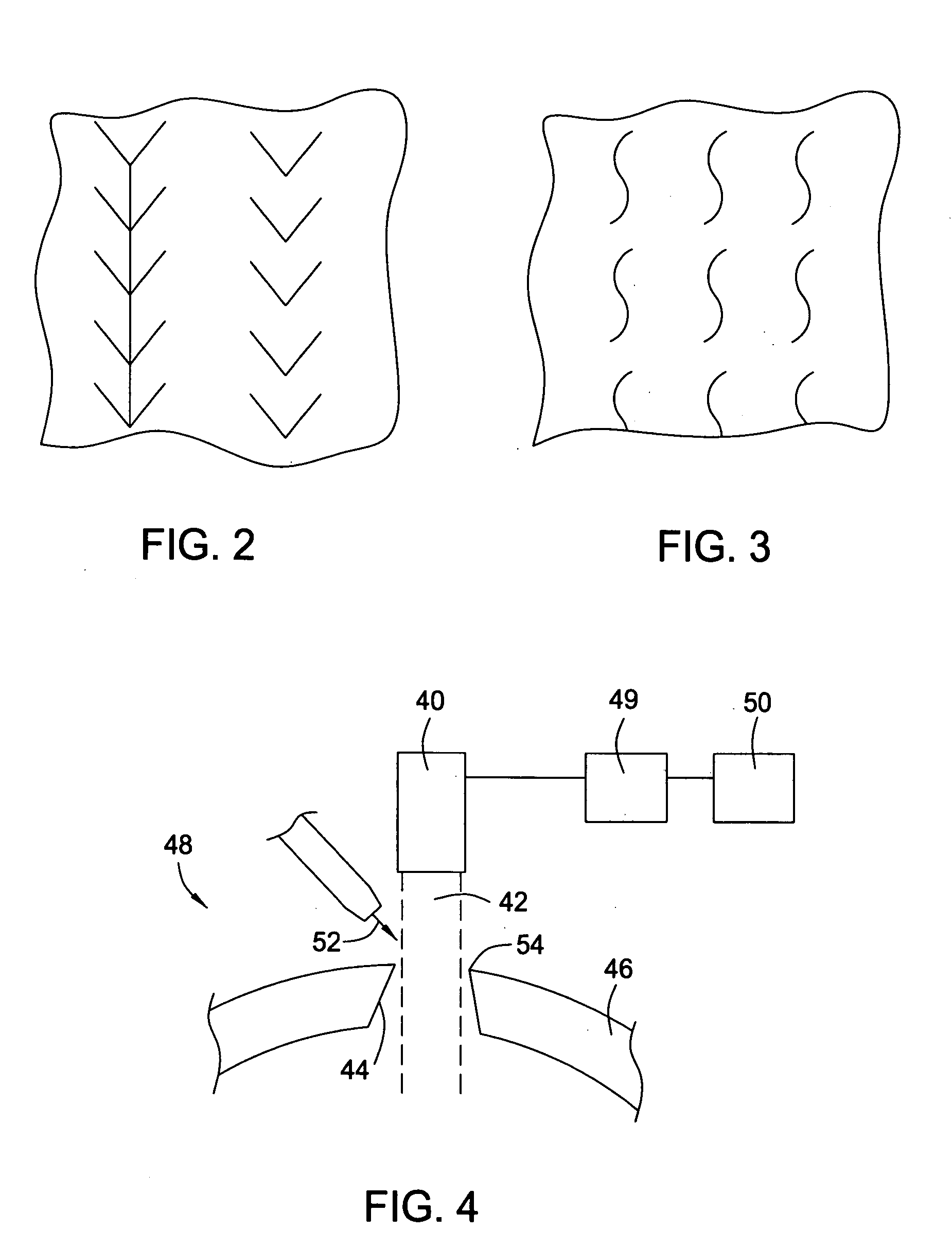
[0022] There are a number of advantages gained by utilising laser to cut the perforations. Firstly, the perforations may be of forms other than those achievable by means of a conventional rotating
cutting tool, and in particular it is possible to cut narrow slots of a serpentine form. Secondly,
laser cutting tools may operate in conjunction with a gas purge, which carries away the vaporised and molten metal, and cools the surrounding material. An
oxygen purge may be utilised to help the
exothermic reaction at high temperatures, but for the present application an
inert gas purge is preferred. However, in addition to merely cooling the metal, the gas purge jet has been found to produce a
quenching effect at the edges of the cut, tending to increase the
hardness of the metal surrounding the cut, particularly the outer edges of the perforations. Of course this is the area of the perforation which is likely to have to withstand the greatest
erosion.
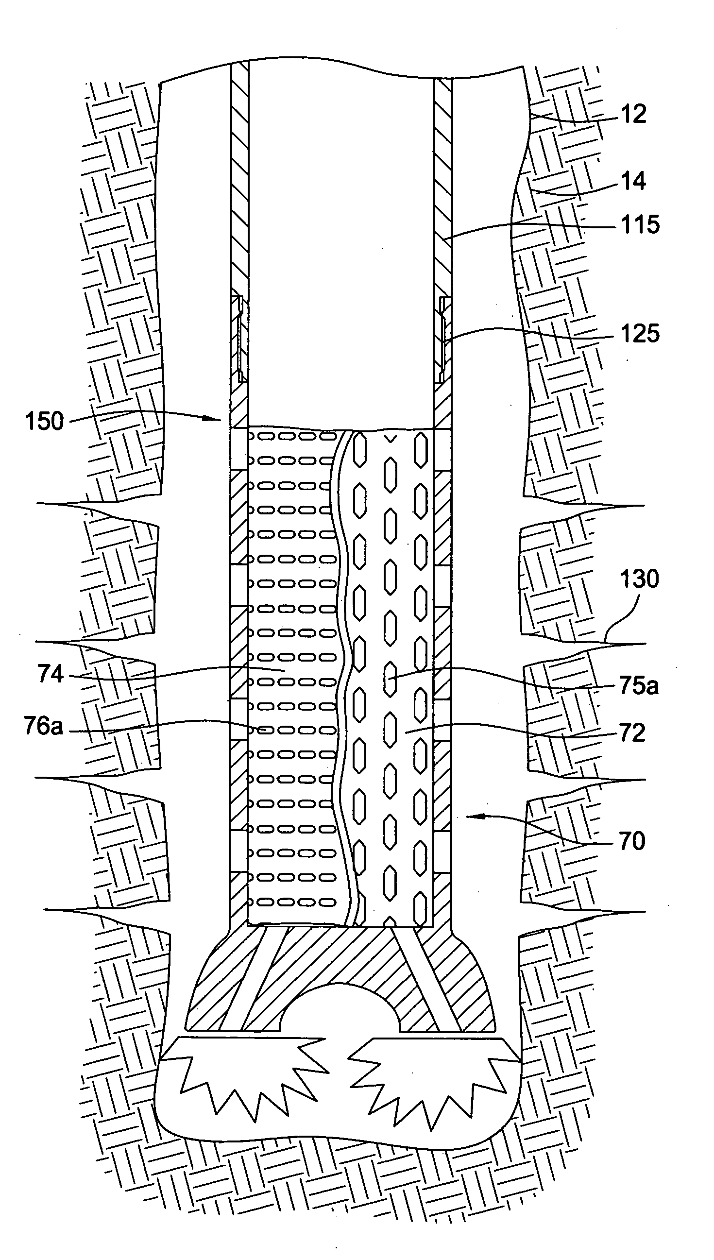
[0024] Surprisingly, it has been found that relatively thin laser-
perforated metal filter sheet may be deformed, and in particular extended, with
minimal risk of tearing. It has been found that the perforations, which are typically originally substantially circular, tend to deform on diametric expansion of the filter sheet to assume the form of elongate slots of width less than the
diameter of the original perforations.
[0025]
Laser-cut perforations tend to have a keystone or trapezoidal section, and the filter sheet is preferably arranged such that the smaller
diameter end of each perforation in the filter sheet is adjacent the outer face of the sheet. It has been found that the laser-perforated sheet is sufficiently robust to obviate the requirement to provide a protective shroud around the exterior of the sheet, thus simplifying the manufacture of the expandable filter arrangement and allowing installation of the laser-perforated sheet within the wellbore without the tear-prone protective shroud. The laser-perforated sheet may be initially provided in planar form, and then wrapped or otherwise formed around the base tube. The edges of the sheet may be joined by any convenient method, such as a seam weld.

