System and method for manufacturing a wing panel

a technology of wing panels and manufacturing methods, applied in the field of wing panels, can solve the problems of requiring substantial human involvement in the manufacturing process of wing panels and, in turn, the assembling of wing panels to form a wing box, and the difficulty in increasing the rate at which wing panels are fabricated

Active Publication Date: 2014-04-03
THE BOEING CO
View PDF6 Cites 18 Cited by
  • Summary
  • Abstract
  • Description
  • Claims
  • Application Information

AI Technical Summary

Benefits of technology

[0005]A system and method are provided in accordance with an example embodiment in order to automate the assembly of a wing panel, such as utilized by commercial aircraft. In one embodiment, the method and system utilize a plurality of operationally separate cells, each of which performs a distinct operation in a largely, if not fully, automated manner. The operationally separate cells may be arranged in a sequential manner such that the work flow begins from a staging cell and then moves, in turn, to a tacking cell, a riveting cell, a splicing cell and a side of body cell. By automating the assembly process and by utilizing operationally separate cells for performing distinct manufacturing operations, the system and method of one embodiment may manufacture wing panels and, in turn, wing boxes more rapidly so as to enable the output to match increased demand.

Problems solved by technology

The manufacturing process for producing a wing panel and, in turn, for assembling the wing panels to form a wing box requires substantial human involvement.
As such, it may be challenging to increase the rate at which wing panels and, in turn, wing boxes are fabricated utilizing the conventional fabrication process.

Method used


Image

  • System and method for manufacturing a wing panel
  • System and method for manufacturing a wing panel
  • System and method for manufacturing a wing panel

Examples


Embodiment Construction

[0025]Embodiments of the present disclosure now will be described more fully hereinafter with reference to the accompanying drawings, in which some, but not all embodiments are shown. Indeed, these embodiments may be embodied in many different forms and should not be construed as limited to the embodiments set forth herein; rather, these embodiments are provided so that this disclosure will satisfy applicable legal requirements. Like numbers refer to like elements throughout.

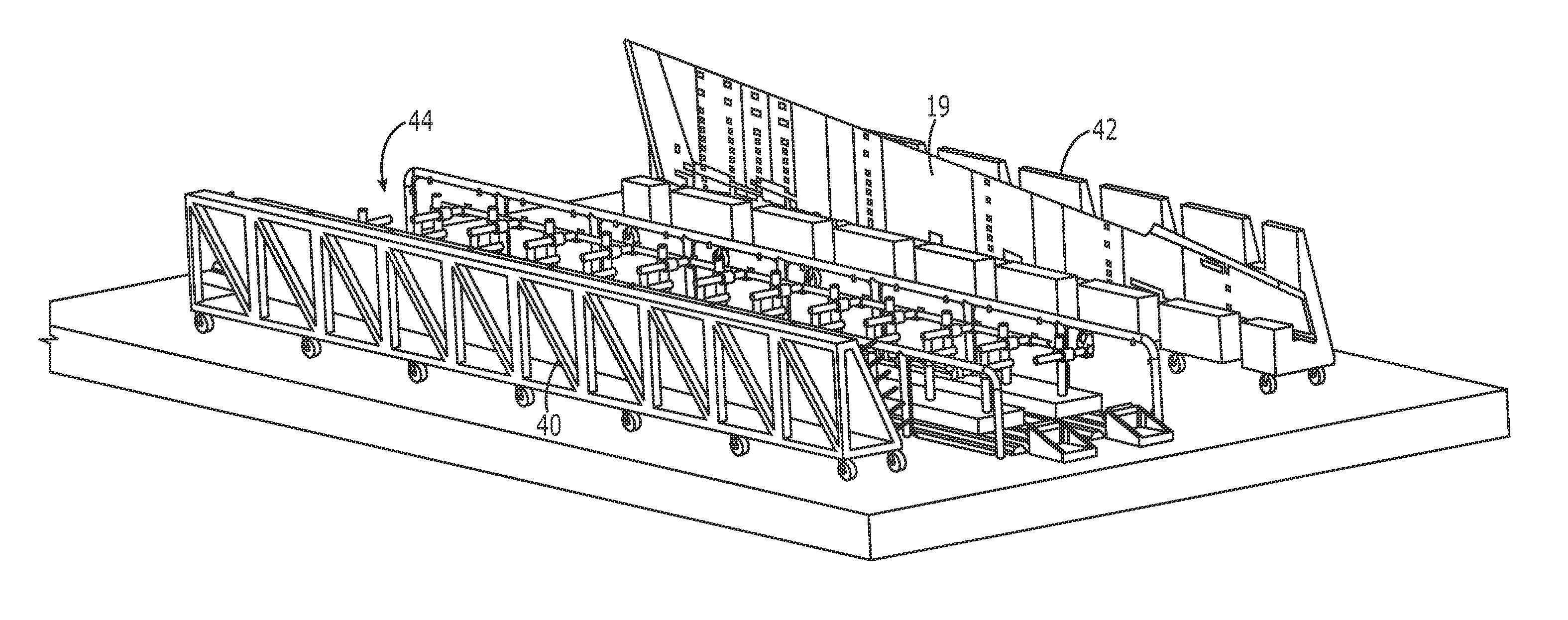
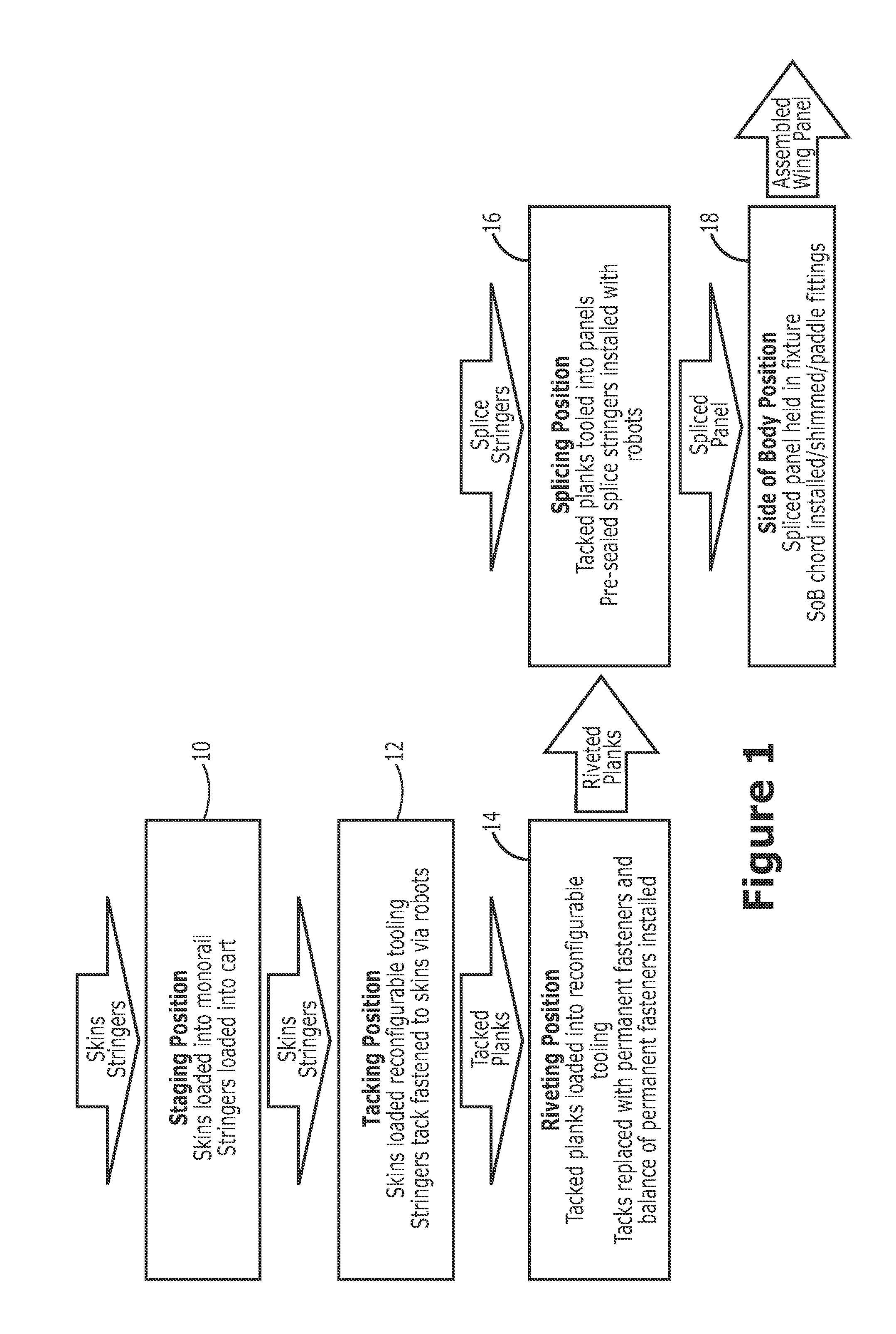
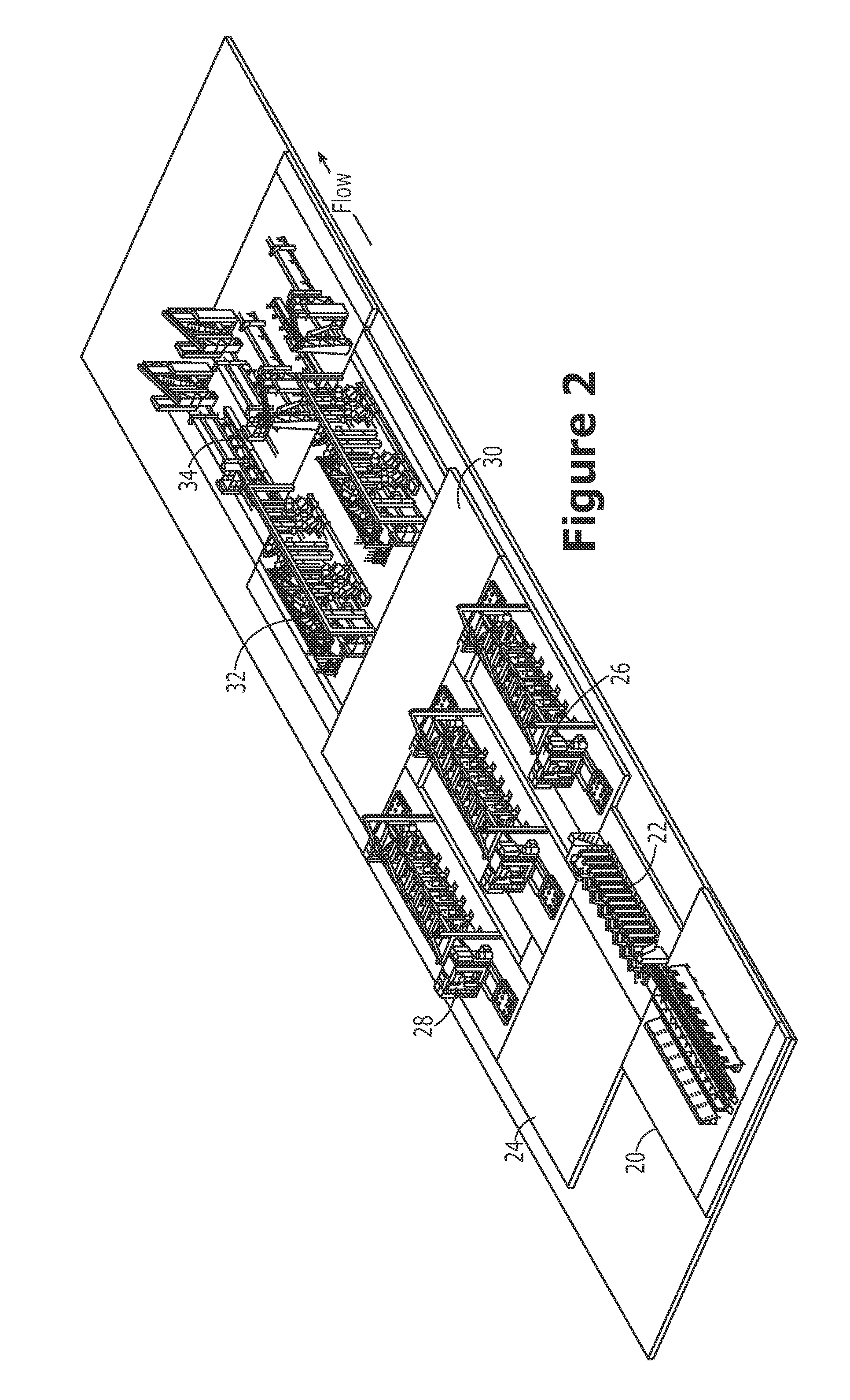
[0026]As shown in FIGS. 1 and 2, the system of one embodiment includes a plurality of sequential operational cells with different manufacturing operations being performed within each cell. The cells are arranged in sequence such that a workpiece moves from a first cell, such as a staging cell 20, to the last cell, such as a side of body cell 34, in order to allow a wing panel to be fabricated. The upper and lower wing panels may then be assembled to form a wing box. As described below the wing skin planks and th...


PUM

PropertyMeasurementUnit
areaaaaaaaaaaa
movementaaaaaaaaaa
tackaaaaaaaaaa

Abstract

A system and method are provided to automate the assembly of a wing panel, such as utilized by commercial aircraft. In the context of a system, a tacking cell is provided that is configured to tack one or more stringers to a skin plank. The system also includes a riveting cell configured to receive a tacked plank from the tacking cell and to rivet the one or more stringers to the skin plank. The system also includes a splicing cell configured to receive a plurality of riveted planks from the riveting cell and to attach one or more splice stringers to the plurality of riveted planks. Further, the system includes a side of body cell configured to receive a spliced panel from the splicing cell and to attach a side of body chord thereto to produce a wing panel.

Description

CROSS REFERENCE TO RELATED APPLICATION[0001]This application is a non-provisional of and claims priority to U.S. provisional patent application No. 61 / 707,360, filed Sep. 28, 2012, the entire contents of which are hereby incorporated by reference.TECHNOLOGICAL FIELD[0002]An example embodiment of the present disclosure relates generally to the manufacture of a wing panel and, more particularly, to the automated assembly of a wing skin planks to form a wing panel utilizing a sequential series of manufacturing cells.BACKGROUND[0003]In order to manufacture a wing panel, a plurality of stringers and a side of body chord are loaded into a fixture to maintain their relative positions. A plurality of wing skin planks are then positioned proximate the stringers and the side of body chord. Once properly positioned, the wing skin planks are clamped to the fixture and thereafter tacked to the stringers and the side of body chord so as to define either an upper wing panel or a lower wing panel. ...

Claims


Application Information

Patent Timeline
Patent Type & Authority Applications(United States)
IPC IPC(8): B23P23/00
CPCB23P23/00B21J15/142B23P2700/01B23P23/06B64F5/50Y10T29/51Y10T29/49622B64F5/10B64F5/00B23P21/00B23P21/004
Inventor SISCO, FARAHNAZ TANNISMITH, DANIEL R.AQUINO, JAYSON J.BATT, EDWARD JOHNBUTTRICK, JAMES N.MICALE, ANTONIO C.JONES, DARRELL D.MUNK, CLAYTON L.COUEVAS, CHRIS G.RAMOS, MARIONAMDARAN, AZITA N.NOOR, NOMAN S.MOTTAZ, DONALD A.
Owner THE BOEING CO
Why Eureka
Try Eureka