Photovoltaic module comprising conductors in the form of strips

Inactive Publication Date: 2014-04-03
COMMISSARIAT A LENERGIE ATOMIQUE ET AUX ENERGIES ALTERNATIVES
View PDF8 Cites 3 Cited by
  • Summary
  • Abstract
  • Description
  • Claims
  • Application Information

AI Technical Summary

Benefits of technology

[0018]The present invention aims at providing a photovoltaic module manufactured according to the pressing technology, enabling to accurately align and to maintain aligned connector strips and en

Problems solved by technology

Further, a cell generally cannot, by itself, deliver an appropriate current and voltage for the operation of current electric equipment.
Besides, photovoltaic cells are fragile elements, most often intended to be used in difficult environmental conditions (rain, hail, etc.).
However, the time for manufacturing a photovoltaic module according to this technique is very long, requires long heating phases to melt the capsule materials, many changes of equipment and many cleaning operations.
This technique is thus expensive.
Further, a degradation of the capsule can be observed in the long run, said capsule then no longer playing its function of protection against air and humidity.
However, such a technique has a number of additional disadvantages relating to electric connectors in the form of strips.
A strip should thus be accurately aligned with its busbar, which thus requires using expensive equipment.
Then, during the use of the photovoltaic module, the means implemented to maintain the connector strips in place are not sufficient.
Indeed, the pho

Method used


Image

  • Photovoltaic module comprising conductors in the form of strips
  • Photovoltaic module comprising conductors in the form of strips
  • Photovoltaic module comprising conductors in the form of strips

Examples


Embodiment Construction

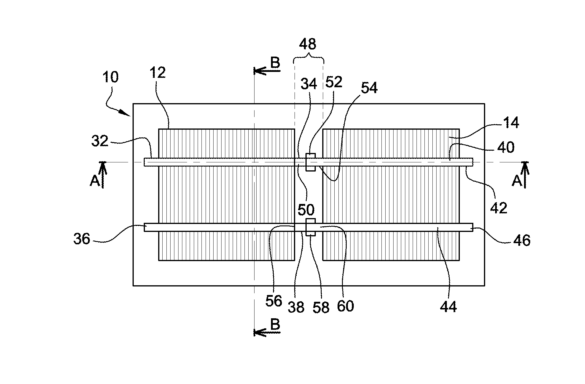
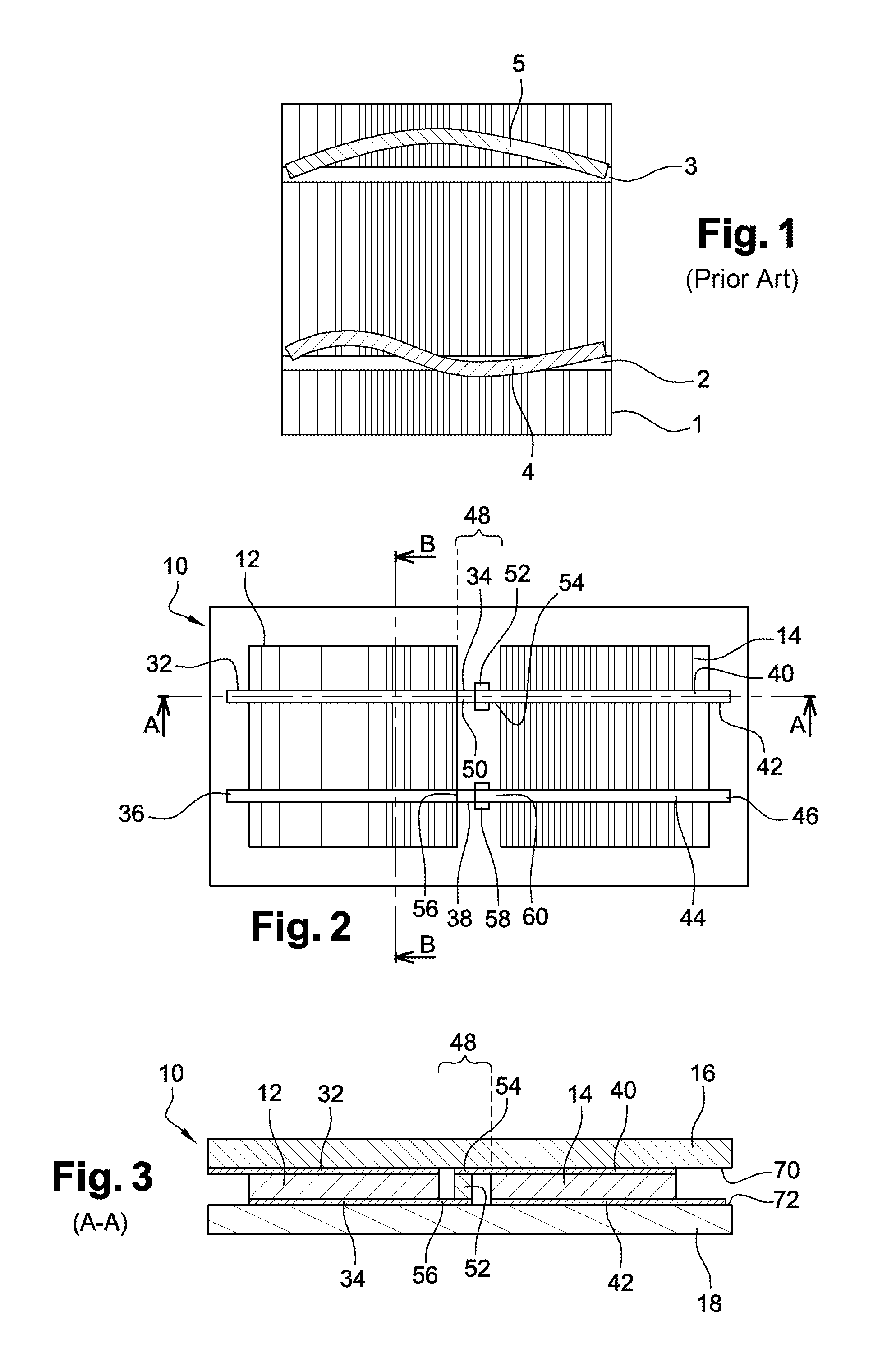
[0059]A photovoltaic module 10 according to the invention is illustrated in FIGS. 2 to 4.

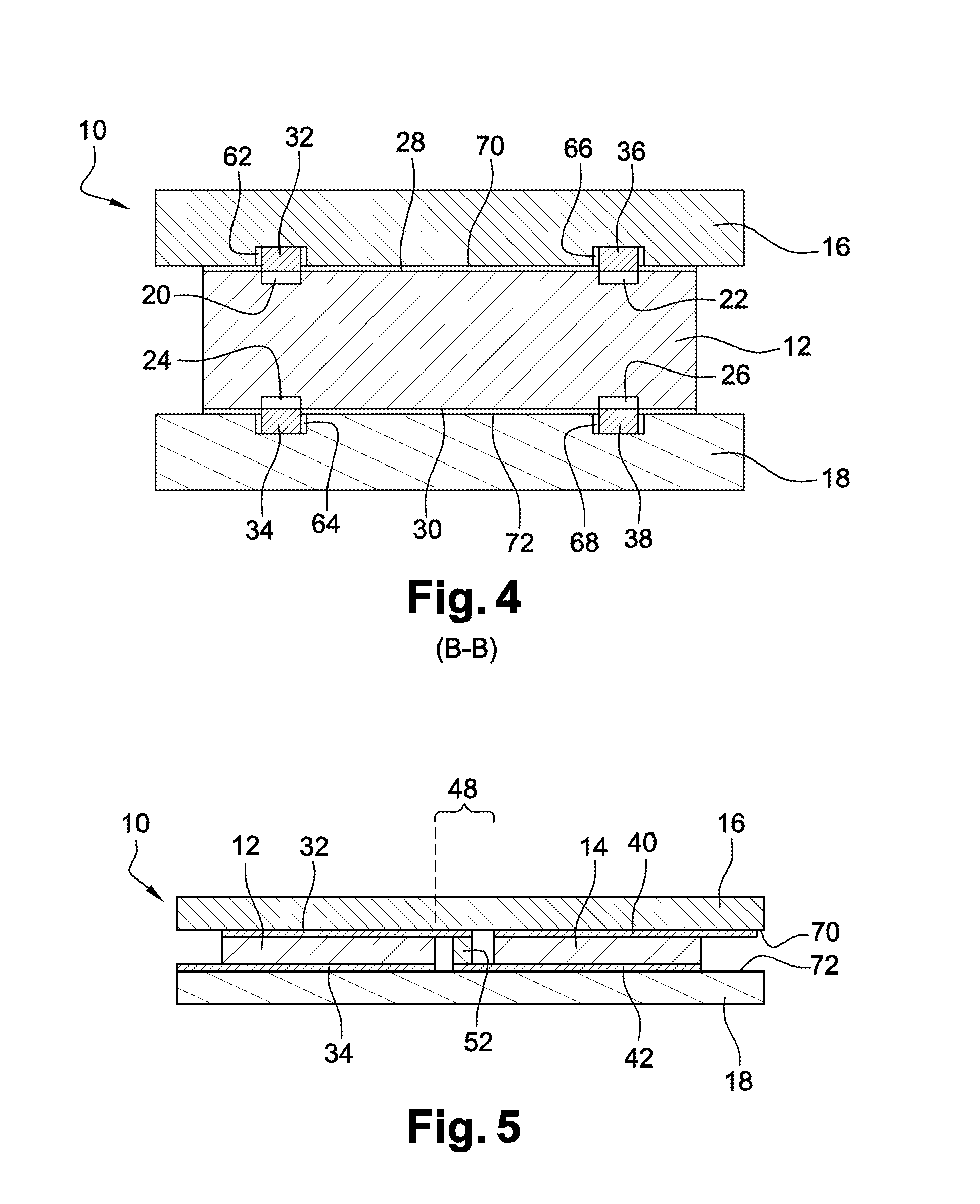
[0060]Module 10 comprises identical homojunction photovoltaic cells 12, 14, two in the example illustrated in FIGS. 2 to 4. Photovoltaic cells 12, 14 are pressed between a transparent upper protective plate 16, or “front” plate, and a lower protective plate 18, or “back” plate. Protective plates 16, 18 are rigid and electrically insulating, and are for example made of tempered glass. Plates 16, 18 are sealed to each other by means of a seal (not shown) to define an air-tight and impervious inner space, said space being filled with a neutral gas, for example, argon, and under a low pressure lower than 500 millibars, and preferably a pressure lower than 300 millibars.

[0061]Each photovoltaic cell 12, 14 further comprises two busbars 20, 22, 24, 26 on each of its surfaces, the two busbars 20, 22 of upper surface 28 of the cell for example corresponding to anode bars of the cell, and the two busbars ...


PUM


Abstract

A photovoltaic module including a transparent upper plate and a lower plate, electrically insulating and sealed to each other to define a tight package; photovoltaic cells pressed between the upper and lower plates; at least two electric contacts arranged on at least a surface of each cell, at least one electric contact being in the form of a strip; and elements electrically connecting the contacts of each cell with the contacts of at least one adjacent cell. At least one strip of each cell is housed in a groove made in the plate in front or it, the groove is defined by: a depth between one quarter and three quarters of the thickness of the strip in a uncompressed state; a width greater than or equal to the width of the strip at 85° C.; and a length greater than or equal to the length of the strip at 85° C.

Description

FIELD OF THE INVENTION[0001]The invention relates to the field of photovoltaic modules, and more specifically to photovoltaic modules having their photovoltaic cells electrically connected by conductive strips, said cells being encapsulated under a low pressure between two plates.BACKGROUND[0002]A photovoltaic cell is a semiconductor device which converts an incident radiation, solar in the case in point, into an electric current by means of a PN junction.[0003]More specifically, the generated electrons are collected by a network of narrow metal electrodes formed in the cell bulk in contact with the anode area(s) thereof, and conveyed by this network to one or several electrodes of larger dimensions, usually called “busbar” and flush with the cell surface.[0004]To convey the electric current outside of the cell, an electric connector called “negative pole” is then placed into contact with each busbar. Similarly, one or several electric connectors are also provided in contact with th...

Claims


Application Information

Patent Timeline
IPC IPC(8): H01L31/02H01L31/048
CPCH01L31/048H01L31/0201H01L31/0504H01L31/0508Y02E10/50H01L31/0488H01L31/05
Inventor VOARINO, PHILIPPELEFILLASTRE, PAUL
Owner COMMISSARIAT A LENERGIE ATOMIQUE ET AUX ENERGIES ALTERNATIVES
Why Eureka
Try Eureka