Method and apparatus for maximizing nitrogen removal from wastewater

Active Publication Date: 2014-04-03
D C WATER & SEWER AUTHORITY +1
View PDF5 Cites 27 Cited by
  • Summary
  • Abstract
  • Description
  • Claims
  • Application Information

AI Technical Summary

Benefits of technology

[0009]Accordingly, the instant disclosure provides a system and method of removing nitrogen from wastewater in a reactor for biological nitrogen removal, wherein an aerobic-anoxic duration and/or a concentration of dissolved oxygen in the reactor is controlled based on a ratio of an [ammonia concentration] to a [sum of nitrite and nitrate concentrations] measured in real time. Typically, the aerobic-anoxic duration and/or the concentration of dissolved oxygen in the reactor is controlled to achieve a ratio of [ammonia concentration] to a [sum of nitrite and nitrate concentrations] that is about 1. Alternatively, the aerobic-anoxic duration and/or the concentration of dissolved oxygen in the reactor may be controlled to achieve a predetermined ratio of [ammonia concentration] to a [sum of nitrite and nitrate concentrations] that is less than or greater than 1. By employing the system and method of the instant disclosure, overall nitrogen removal is maximized because denitrification (dependent on COD input) and subsequent ammonia oxidation balance each other while also favorin

Problems solved by technology

It is difficult to incorporate control strategies in the above-mentioned mechanisms to achieve stable SND performance.
Control of NOB repression in low strength waste streams such as domestic wastewater remains a challenge and is the subject of this disclosure.
However, knowledge of controlling FA inhibition to obtain stable nitritation is more limited since NOB adaptation has been reported (see Turk and Mavinic, 1989; and Wong-Chong and Loehr, 1978, the dis

Method used


Image

  • Method and apparatus for maximizing nitrogen removal from wastewater
  • Method and apparatus for maximizing nitrogen removal from wastewater
  • Method and apparatus for maximizing nitrogen removal from wastewater

Examples


examples

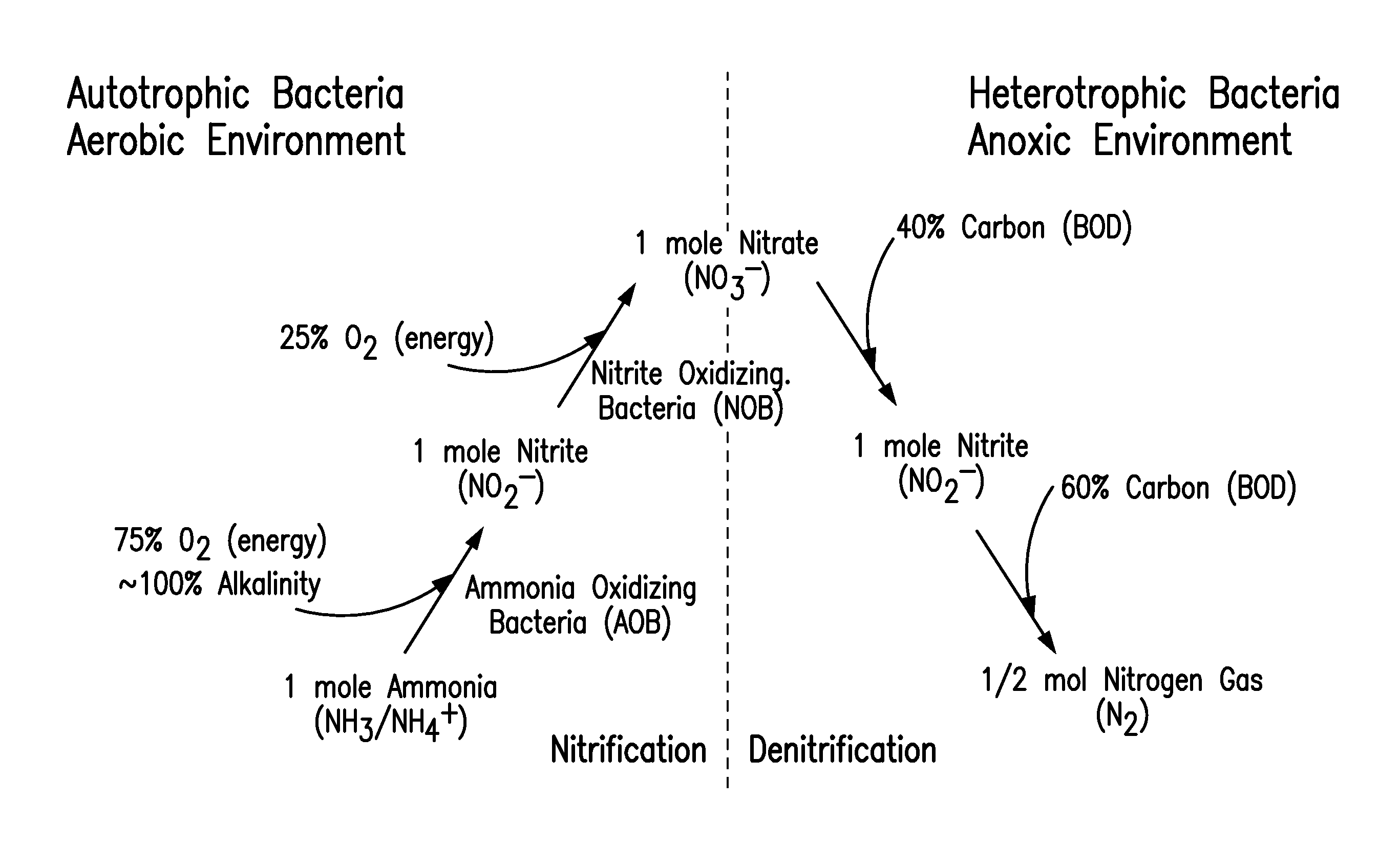
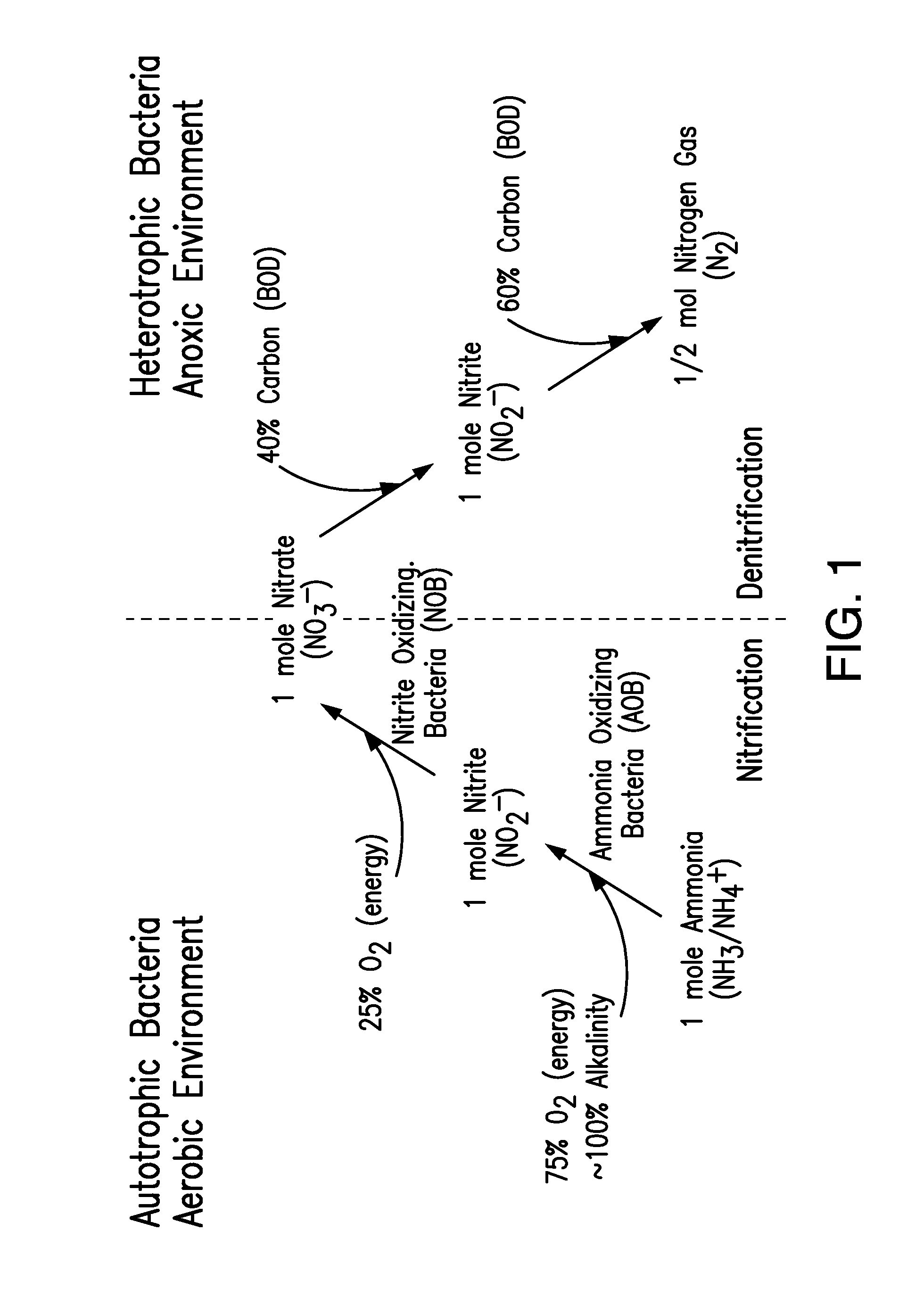
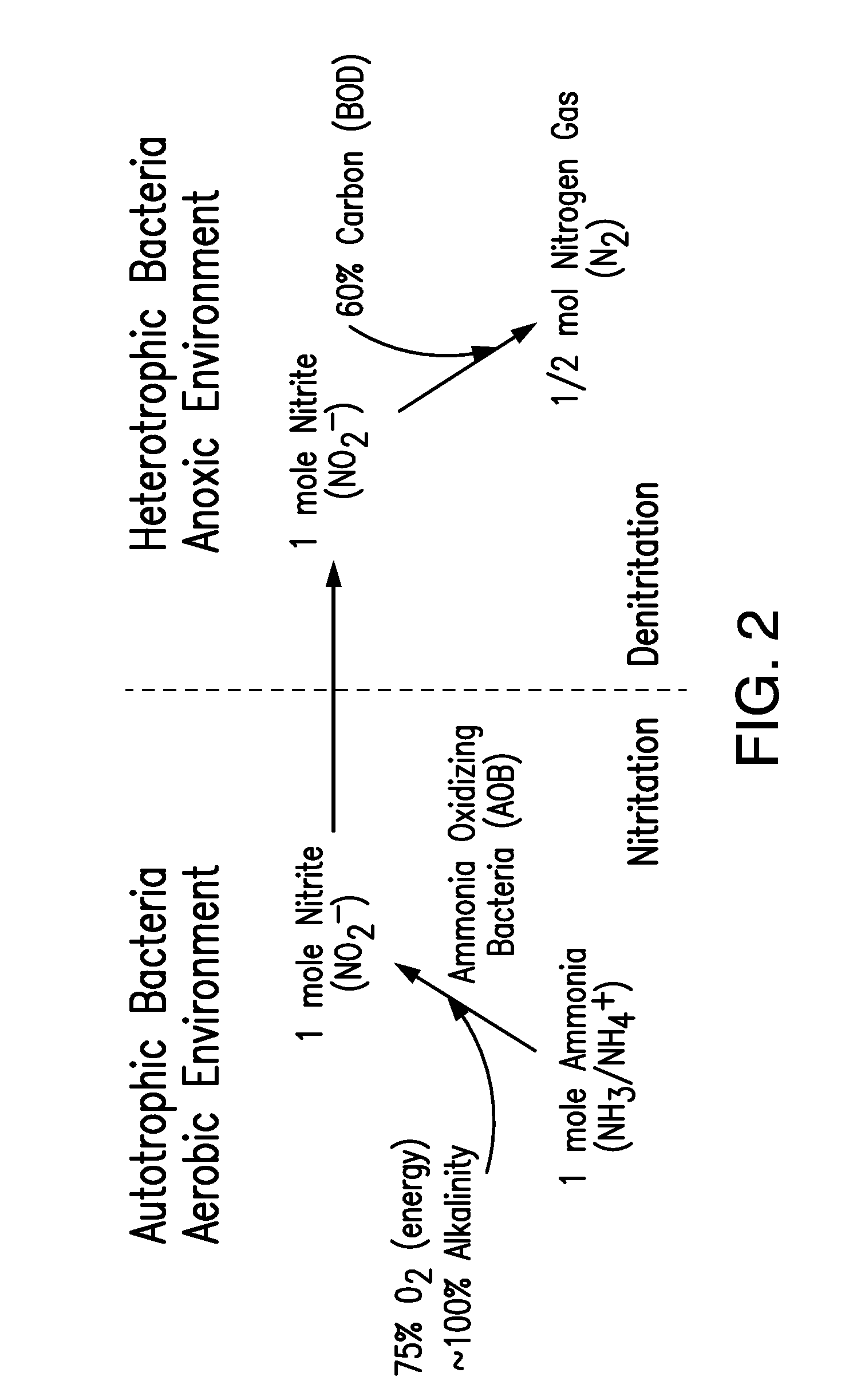
[0050]The system for removing nitrogen in a reactor for biological nitrogen removal from wastewaters of the present disclosure was operated with 2-3 hr hydraulic residence time (HRT), ˜5 day SRT, 3500±500 mg / L mixed liquor suspended solids (MLSS) at 25° C. The reactor was operated under the AVN control strategies set forth at paragraph [0047] (above) and shown in FIGS. 5-6. FIG. 9 represents the NOB repression that was observed. The AVN controller performance is demonstrated in FIG. 12. As seen in FIG. 13, high TIN removal, wherein the removal was dependent on COD input, was also achieved using the same operating conditions.

Relevant Acronyms:

[0051]AOB: ammonia oxidizing bacteria[0052]BNR: biological nutrient removal[0053]COD: chemical oxygen demand[0054]C / N: Carbon to nitrogen ratio[0055]DO: dissolved oxygen[0056]FA: free ammonia[0057]HDO: high DO[0058]HRT: hydraulic residence time[0059]LDO: low DO[0060]NOB: nitrite oxidizing bacteria[0061]NOx: Nitrate[0062]NOx—N: Nitrate-nitrogen p...


PUM


Abstract

A reactor and control method thereof to maximize nitrogen removal and minimize aeration requirement through control of transient anoxia and aerobic SRT, repression of NOB, and control of dynamic DO concentrations or aeration interval by keeping the reactor NH4 and NOx concentrations approximately equal has been proposed. Controls described in this invention maximizes the potential for TIN removal through nitrification, limited nitritation, nitritation, denitrification, limited denitritation, denitritation making use of 1) real time measurement of ammonia, nitrite, nitrate, 2) operational DO and the proper use of DO setpoints, and 3) proper implementation of transient anoxia within a wide range of reactor configurations and operating conditions.

Description

BACKGROUND[0001]Simultaneous nitrification and denitrification (SND) in a single tank is highly desirable compared to the conventional systems, since separate tanks and recycling of mixed liquor nitrate from the aerobic nitrifying zone to the anoxic denitrifying zone is not required. The benefits of SND are further extended by exploiting the nitrite shunt pathway as has been demonstrated by the use of aeration duration control with ORP (see Guo et al. 2009, the disclosure of which is expressly incorporated by reference herein in its entirety) and ammonia pH profile (see Peng, et al. 2004, the disclosure of which is expressly incorporated by reference herein in its entirety). The reactor microenvironments (aerobic and anoxic zones developing within reactor due to combination of poor mixing and reactor design) and the floc microenvironments (aerobic an anoxic zones developing within the activated sludge flocs) have been postulated as possible mechanisms for SND (see Daigger et al. 200...

Claims


Application Information

Patent Timeline
IPC IPC(8): C02F3/30
CPCC02F3/303C02F3/307C02F3/305C02F3/006C02F3/301C02F3/302C02F2209/005C02F2209/006C02F2209/14C02F2209/15C02F2209/22Y02W10/10
Inventor REGMI, PUSKERMILLER, MARKBOTT, CHARLES B.
Owner D C WATER & SEWER AUTHORITY
Why Eureka
Try Eureka