Reference voltage generator

a reference voltage and generator technology, applied in the direction of electric variable regulation, process and machine control, instruments, etc., can solve the problem of excessive saving of layout area, achieve good power supply rejection ratio (psrr), save layout area excessively, and reduce system voltage

Inactive Publication Date: 2014-04-03
NOVATEK MICROELECTRONICS CORP
View PDF3 Cites 30 Cited by
  • Summary
  • Abstract
  • Description
  • Claims
  • Application Information

AI Technical Summary

Benefits of technology

[0017]The embodiment of the disclosure set forth a reference voltage generator, which may save the layout area excessively. The reference voltage generator of the embodiment of the disclosure have good power supply rejection ratio (PSRR) with a lower system voltage as well as the capability of stabilizing a reference voltage.
[0032]In the view of foregoing description, the embodiment of the disclosure set forth a reference voltage generator, which generates a first gate-source voltage and a second gate-source voltage by operating the first MOS transistor and the second MOS transistor in the sub-threshold region. In addition, a voltage drop across the two terminals of the first impedance providing element is formed by utilizing the first gate-source voltage and the second gate-source voltage, so as to generate the first current having a positive temperature coefficient. As a result, the desired reference voltage equals to the first voltage plus the second gate-source voltage. Furthermore, an excessive layout area occupied by the bipolar junction transistors can be avoided under such circuit architecture using the MOS transistor as the main components.

Problems solved by technology

The embodiment of the disclosure set forth a reference voltage generator, which may save the layout area excessively.

Method used


Image

  • Reference voltage generator
  • Reference voltage generator
  • Reference voltage generator

Examples


Embodiment Construction

[0049]Reference will now be made in detail to the present exemplary embodiments of the disclosure, examples of which are illustrated in the accompanying drawings. Wherever possible, the same reference numbers are used in the drawings and the description to refer to the same or like parts.

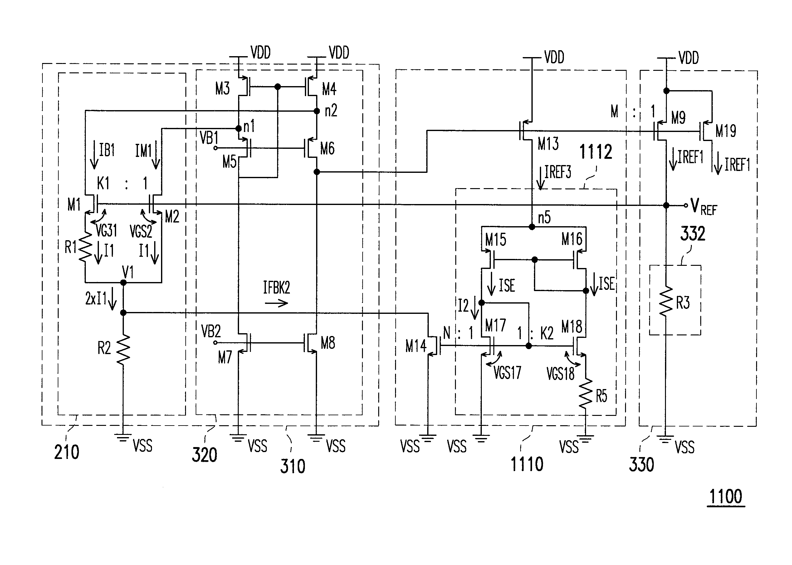
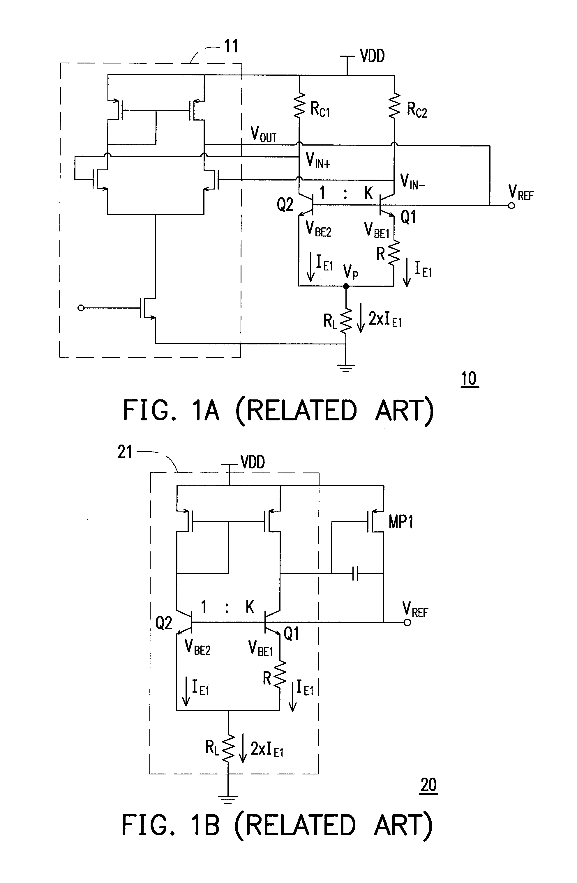
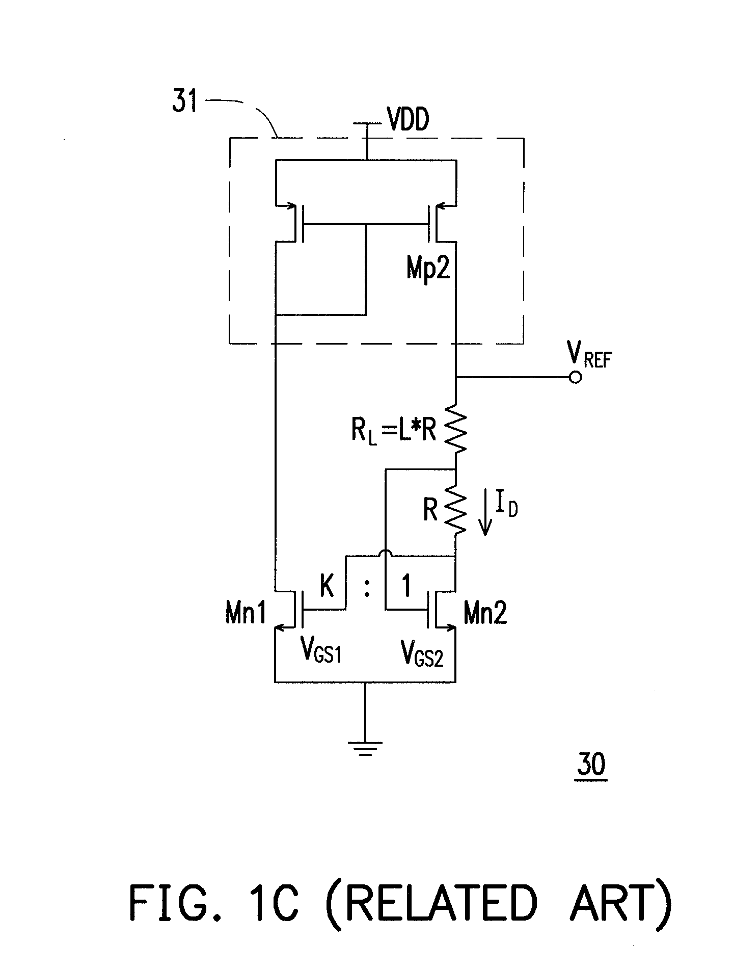
[0050]The design mechanism of the disclosure is based on the metal-oxide semiconductor (MOS) transistors as the main elements, the MOS transistors operate in the sub-threshold region, so as to have a gate voltage of the MOS transistors has a voltage having negative temperature coefficient. Accordingly, an excessive layout area occupied by the bipolar junction (BJT) transistors can be avoided. In addition, since there are no current at a gate of the MOS transistors, the amount of current is not affected by the fabrication or any other factors as it may have in the conventional art using BJT transistors, which causes the reference voltage to fluctuate.

[0051]According to one of the exemplary embodiment...


PUM

PropertyMeasurementUnit
bias voltageaaaaaaaaaa
temperatureaaaaaaaaaa
temperature coefficientaaaaaaaaaa

Abstract

A reference voltage generator including a reference voltage generating unit is provided. The reference voltage generating unit receives a first bias voltage current and a first mirror current and generates a reference voltage. The reference voltage generating unit includes a first metal-oxide-semiconductor (MOS) transistor, a second MOS transistor, a first impedance providing element and a second impedance providing element. The first and the second MOS transistors operate in a sub-threshold region so as to generate a first gate-source voltage and a second gate-source voltage having a negative temperature coefficient. The first impedance providing element is configured to generate a first current having a positive temperature coefficient. The second impedance providing element is configured to generate a first voltage having a negative temperature coefficient at its first terminal. The reference voltage is equal to a sum of the second gate-source voltage and the first voltage.

Description

CROSS-REFERENCE TO RELATED APPLICATION[0001]This application claims the priority benefit of Taiwan application serial no. 101136000, filed on Sep. 28, 2012. The entirety of the above-mentioned patent application is hereby incorporated by reference herein and made a part of this specification.BACKGROUND OF THE DISCLOSURE[0002]1. Field of the Disclosure[0003]The disclosure is related to a reference voltage generator, and particularly a reference voltage generator employing metal-oxide semiconductor transistors as main components.[0004]2. Description of the Related Art[0005]A digital-to-analog converter (DAC), an analog-to-digital converter (ADC), or a regulator requires at least a reference voltage that is fixed and constant. It is best that the reference voltage is regenerated for every power-up with stability. An ideal reference voltage is not to be affected by the fabrication variation, changes in operational temperature, and variations in power source. The bandgap reference circui...

Claims


Application Information

Patent Timeline
Patent Type & Authority Applications(United States)
IPC IPC(8): G05F1/46
CPCG05F1/462G05F3/30
Inventor HU, MIN-HUNGHUANG, CHIU-HUANGWU, CHEN-TSUNGHUANG, JUIN-WEISU, PIN-HAN
Owner NOVATEK MICROELECTRONICS CORP
Why Eureka
Try Eureka