Extrusion press

a technology of extrusion press and press body, which is applied in the direction of extrusion control device, forging/pressing/hammering apparatus, servomotor, etc., can solve the problems of heat and burnout at the armature of the electric motor, uneven load times of the drive (on-load) operation, and variation in the dynamic and thermal fatigue degree and remaining service life of the component device. , to achieve the effect of suitable operation management and reduction of power was

Inactive Publication Date: 2014-04-10
UBE MASCH CORP LTD
View PDF2 Cites 14 Cited by
  • Summary
  • Abstract
  • Description
  • Claims
  • Application Information

AI Technical Summary

Benefits of technology

[0024]In the extrusion press system of the present invention, the order of selection of hydraulic pumps which are selectively controlled to be driven in accordance with the speed setting of the extrusion press is controlled by a program which progressively advances with each predetermined molding cycle, the unevenness of the dynamic and thermal fatigue degrees of the hydraulic devices which form the hydraulic circuit of the hydraulic press, the electric motors which drive the hydraulic pumps, the control devices, etc. can be eliminated, the dynamic and thermal fatigue degrees and remaining service life of the component devices can be made even, and suitable operational management is possible.
[0025]In the extrusion press of the present invention, when providing the necessary discharge rate in t

Problems solved by technology

In this way, in the hydraulic pumps, the load times of the drive (on-load) operations become uneven.
There was therefore the problem that variation occurs in the dynamic and thermal fatigue degrees and remaining service lifetime of the component devices.
Further, with the method of control of continuously stopping the high voltage (for example, 3.3 kV or 6.6 kV), high capacity (for example, 100 kW or more) electric motors fo

Method used


Image

  • Extrusion press
  • Extrusion press
  • Extrusion press

Examples


Embodiment Construction

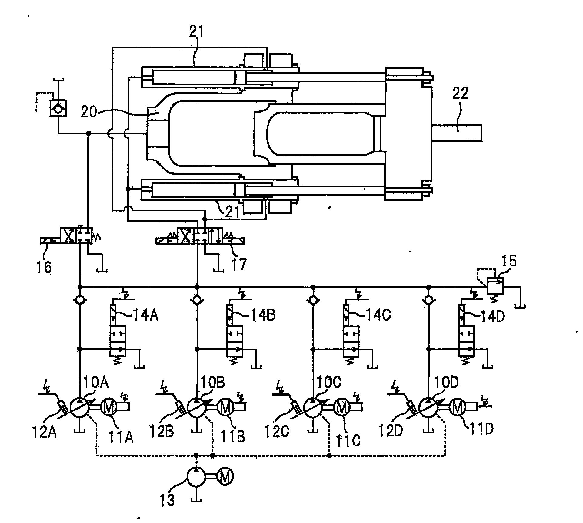
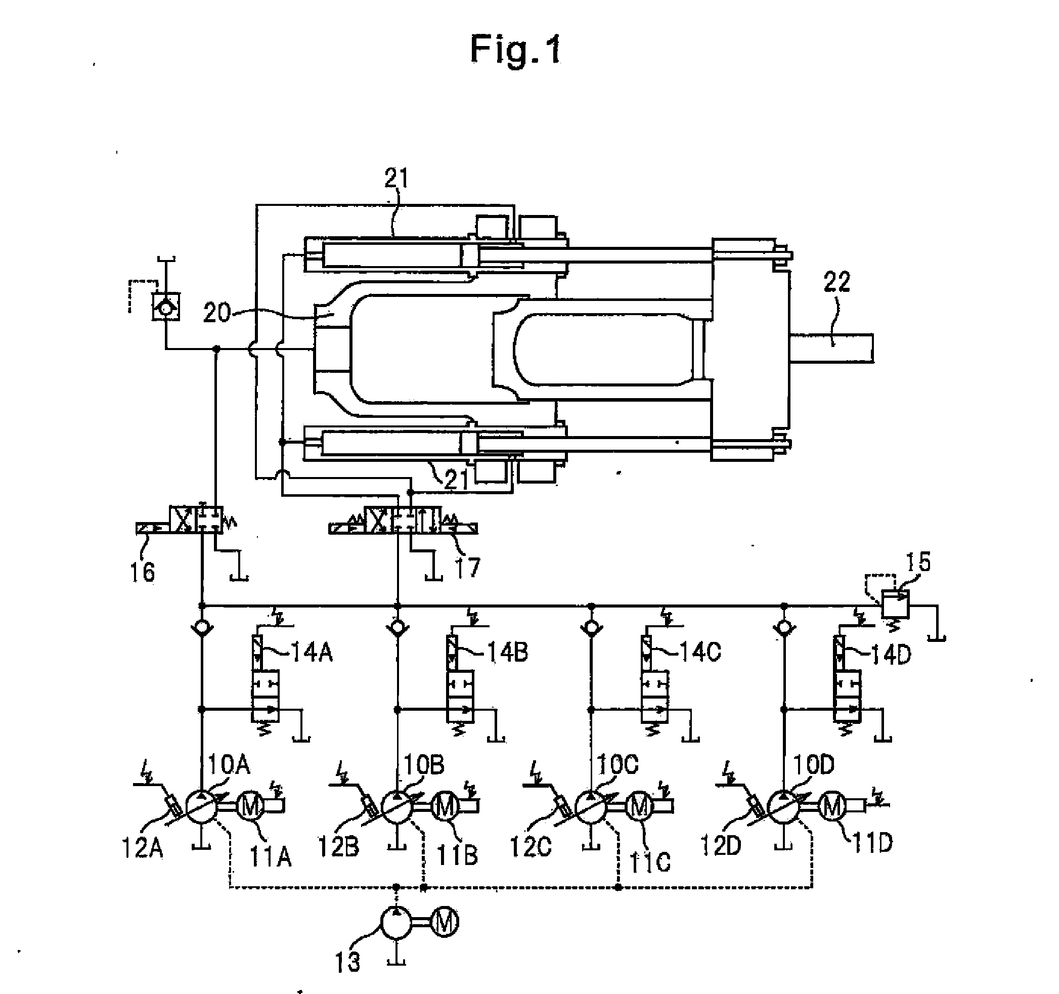
[0035]Below, embodiments of the extrusion press of the present invention will be explained with reference to the drawings. FIG. 1 is an explanatory view of a hydraulic circuit of an extrusion press according to an embodiment.

[0036]Reference notations 10A to 10D which are shown in the figures are variable capacity type hydraulic pumps, while 11A to 11D are electric motors which drive the hydraulic pumps. Reference notations 12A to 12D are discharge rate control means of the variable capacity type hydraulic pumps. These use flow rate control signals to control the tilt angles of the hydraulic pumps and adjust the discharge rates. Further, each of the variable capacity type hydraulic pumps 10A to 10D is set with the same maximum discharge rate. Reference notation 13 indicates a fixed discharge capacity type hydraulic pump which supplies pilot pressure to the devices which form the hydraulic circuit.

[0037]Reference numerals 14A to 14D are solenoid valves which selectively switch between...


PUM

PropertyMeasurementUnit
Temperatureaaaaaaaaaa
Thermal fatigueaaaaaaaaaa

Abstract

The present invention provides an extrusion press which eliminates unevenness of dynamic and thermal fatigue degrees of the hydraulic devices which form the hydraulic circuit in the extrusion press, the electric Motors which drive the hydraulic pump, the control devices, etc., which makes the dynamic and thermal fatigue degrees and remaining service lives of the component devices even, and which is excellent in energy saving effect.
An extrusion press which has a plurality of variable capacity type hydraulic pumps connected to it in parallel for supplying working oil to hydraulic cylinders of the extrusion press, uses a preset working speed as the basis to find the required discharge rate of the hydraulic pumps, and selectively controls the drive operations of the hydraulic pumps, wherein the order of selection of the hydraulic pumps which are selectively controlled in drive operation is controlled by a program which progressively advances when a predetermined number of molding cycles are completed.

Description

TECHNICAL FIELD[0001]1. Cross-Reference to Related Application[0002]The present invention claims priority based on Japanese. Patent Application No. 2011-132853 which was filed on Jun. 15, 2011, whose entire content is incorporated by reference in this Description.[0003]The present invention relates to an extrusion press which is provided with a plurality of variable capacity type hydraulic pumps and which is used for extrusion of aluminum alloy etc.[0004]2. Background Art[0005]In general, when extruding a metal material, for example, an aluminum or aluminum alloy material, or other extrusion material (billet) by an extrusion press, a stem is attached to the front end of a main ram which is driven by hydraulic cylinders. The billet is stored in a container by the stem in a state pushing the container against a die. Further, the main ram is made to advance by a drive operation of the hydraulic cylinders to push the billet by the stem. Therefore, a product which is shaped is extruded f...

Claims


Application Information

Patent Timeline
IPC IPC(8): B21C23/21F15B11/00F15B11/02H02P5/00
CPCB21C23/211F15B11/0426F15B2211/20546F15B2211/20576H02P29/60
Inventor YAKUSHIGAWA, ATSUSHIYAMAMOTO, TAKEHARU
Owner UBE MASCH CORP LTD
Why Eureka
Try Eureka