Distributed energy storage and power quality control in photovoltaic arrays

a photovoltaic array and energy storage technology, applied in secondary cells servicing/maintenance, electrochemical generators, greenhouse gas reduction, etc., can solve the problems of increasing the size of the centralized battery bank, increasing the cost of thermal management, and having to use expensive forced air or liquid cooling approaches to achieve thermal management. , the function of solar-pv can be enhanced, and the control function can be advanced

Active Publication Date: 2014-04-17
WOLTER JAMES F
View PDF1 Cites 48 Cited by
  • Summary
  • Abstract
  • Description
  • Claims
  • Application Information

AI Technical Summary

Benefits of technology

[0017]In another aspect of this invention a solar panel combined with a battery and a micro-inverter can provide for an augmented “AC” panel's utility by providing load leveling and after “solar-hours” power to their load. The micro-inverter's internal circuitry can be readily augmented with the necessary logic and power control elements to control the charging, discharging, “gas-gauge”, cycle history, diagnostics, and reporting functions to display and manage stored energy at a master-system level. These micro-inverters now have advanced sensing, control, reporting, and diagnostics functions for the solar-PV function which can be enhanced by adding energy storage capabilities to the individual panel / micro-inverter unit. This augmentation creates a stored energy utility to “AC” panel systems which enables load-following and load-leveling capabilities which cannot be provided by a collection of micro-inverters alone. This configuration preserves the advantage of having short D.C.-links in the power system and utilizes the existing distributed inverter system to provide solar plus stored energy power operation of the system.
[0018]In another aspect of the invention, advantage is taken of configuring A.C. panels such that systems integration is simplified to various transformer interconnections and power distribution panels and D.C. wiring and large central inverters are eliminated altogether. If bidirectional micro inverters are used such that power and information flows both from the solar power system to the grid and from the grid back to individual power units, the net-benefit of having energy storage within the system combined with smart-control adapts the system to “smart-grid” control for use by a larger power provider (a Utility or smaller distributed, community energy storage system in a micro-grid).
[0019]In another aspect of this invention, conventional framed PV panel installations can become distributed energy generation and energy storage on a string-by-string basis and eliminate the need for central battery-banks and in the cases of using micro-inverters, central inverters would also be eliminated. Ideally the level of integration would be determined by the independent mounting systems employed in the larger system and connections would still be made in conventional combiner boxes. As micro-inverters become more powerful—it may become convenient to move distributed energy storage, micro-inversion, and control to the combiner box itself.

Problems solved by technology

While it has been common practice to use centralized battery storage systems with solar-PV systems (especially in off-grid systems), in almost all cases centralized battery banks are more expensive, less safe, and less reliable than using many panel-mounted battery, capacitor, or combination battery and capacitor elements having the collective, equivalent energy storage capacity of the larger central energy storage device.
ery. As battery systems increase in size, automotive designers for example, are forced to use expensive forced air or liquid cooling approaches to thermally manage their battery sys
Catastrophic battery failures release very large and dangerous amounts of energy—sometimes explosively and always liberating large quantities of heat energy.
Most of these failures start with one-cell and quickly migrate in chain-reaction fashion to adjacent cells and are limited only by the sum of the collected proximal cells—large central batteries can have very dangerous failure modes whereas a failure on a single solar-panel mounted battery is limited by the small size of the battery and the physical isolation of the solar panel within the larger system.

Method used


Image

  • Distributed energy storage and power quality control in photovoltaic arrays
  • Distributed energy storage and power quality control in photovoltaic arrays
  • Distributed energy storage and power quality control in photovoltaic arrays

Examples


Embodiment Construction

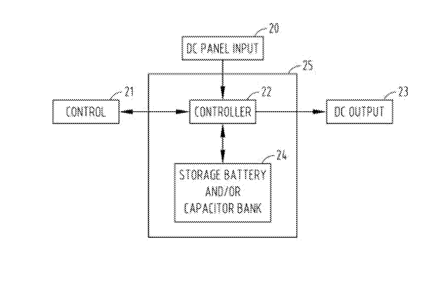
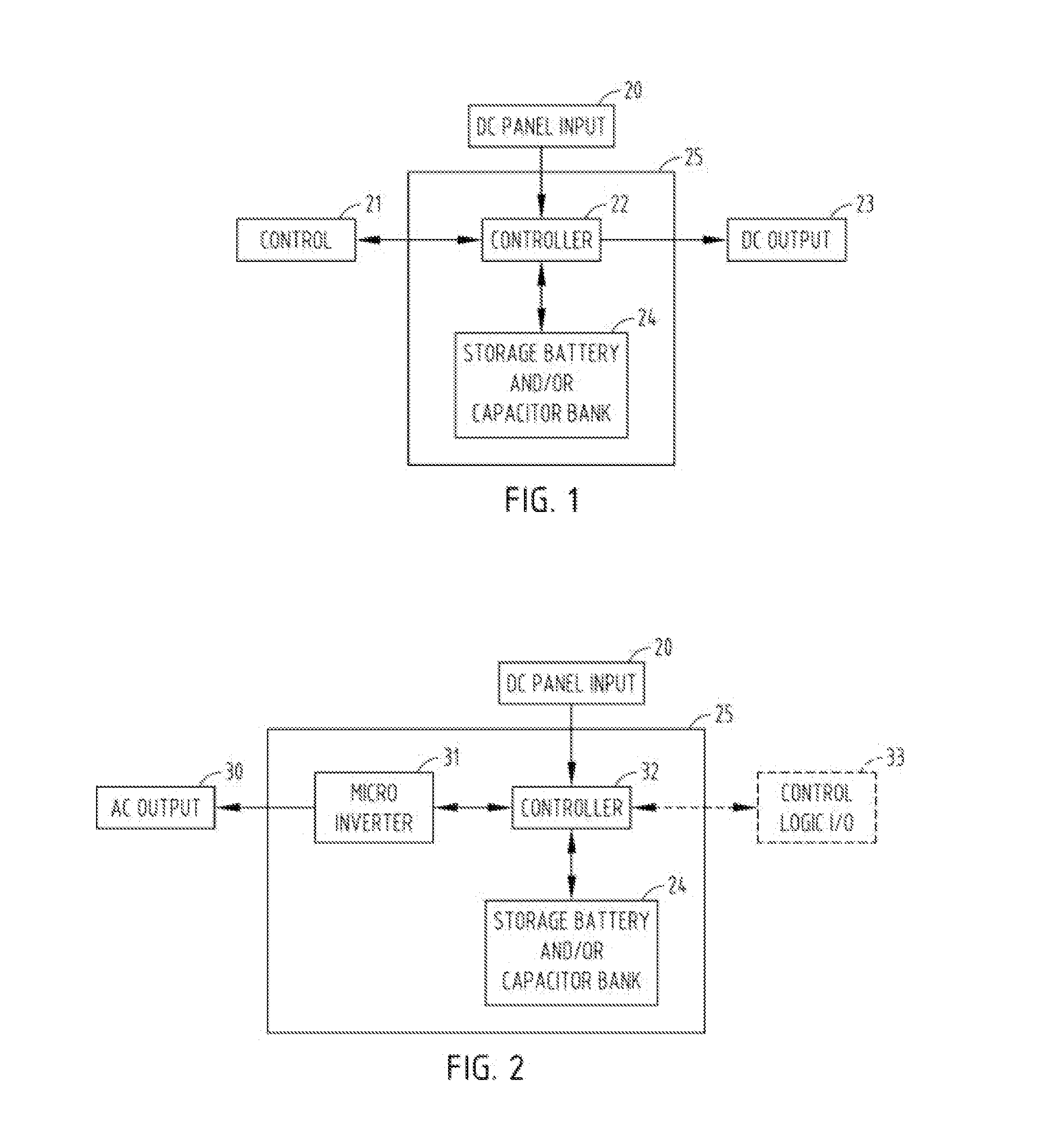
[0027]A solar power generation, storage, and control system comprises a solar panel 25 or a plurality of solar panels or solar laminates or an assembly of concentrating PV elements, combined with an associated energy storage system 24 and an electronic control 22 circuit which senses and reports systems' operating parameters and either under internal settings or external control 21 stores and releases energy as Direct Current electrical power 23 as needed and as is available. (see FIG. 1).

[0028]A power generation, storage, and control system 25 comprises a solar panel 20 or a plurality of solar panels or laminates or an assembly of concentrating PV elements, combined with an associated energy storage system 24, a micro-inverter 31 for A.C. output, an electronic control circuit 32 which senses and reports systems' operating parameters, and either under internal settings or external control 33 stores and releases energy as alternating current electrical power as is needed or available...


PUM


Abstract

A solar electric system comprises photovoltaic elements having integrated energy storage and control, ideally on each PV-panel. The energy storage media may be primary or secondary cylindrical cells interconnected into a battery and/or an array of capacitors (or super-capacitors) and are accompanied by an electronic control circuit which may perform a variety of functions, including but not limited to: power quality control, load following, pulse powering, active line transient suppression, local sensing, remote reporting, wireless or wired communications allowing two way programmable control through local or remote operation. The operation of the system may yield direct current or with the integration of bidirectional micro-inverters create distributed alternating current generation enhanced with energy storage and control two way energy flows between the solar system and the grid.

Description

CROSS REFERENCE TO RELATED APPLICATION [0001]This application claims benefit under 35 U.S.C. Section 111(e) of provisional application Ser. No. 61 / 547,689 filed Oct. 15, 2011 entitled DISTRIBUTED ENERGY STORAGE AND CONTROL IN PHOTOVOLTAIC ARRAYS, the essential content of which is incorporated herein.BACKGROUND OF THE INVENTION [0002]The present invention relates to photovoltaic (PV) solar electric power systems and concentrated photovoltaic (CPV) solar electric power systems, and more particularly to direct-conversion, photovoltaic solar-electric systems having energy storage and power-quality control devices physically mounted on, and electrically integrated with individual PV-panels, single CPV devices, limited numbers of panels as may be in close physical proximity (for example, on a single PV-panel, a mounting structure holding a plurality of such PV panels and interconnected electrically, or integrated into a single “string” which has the purpose of creating a desired “take-off...

Claims


Application Information

Patent Timeline
Patent Type & Authority Applications(United States)
IPC IPC(8): H02J7/35
CPCH02J3/32Y02E70/30H02J7/35H02S50/00Y02B10/10Y02E10/56Y02P80/20Y02E60/10H01M10/48H02S40/36H01L31/053H02S40/32H02S40/38H01M10/425
Inventor WOLTER, JAMES F.
Owner WOLTER JAMES F
Why Eureka
Try Eureka