Apparatus and method for demonstrating quantized conductance

a conductance and apparatus technology, applied in resistance/reactance/impedence, material analysis, instruments, etc., can solve the problems of difficult to adopt the approach in most physics labs, and achieve the effect of reducing the diameter of the constraint (weak area), reducing the cost and robustness of the device, and breaking easily and repeatedly

Inactive Publication Date: 2014-04-17
MIAMI UNIVERSITY
View PDF0 Cites 9 Cited by
  • Summary
  • Abstract
  • Description
  • Claims
  • Application Information

AI Technical Summary

Benefits of technology

[0024]Applicants have developed an inexpensive and robust device and method that can be used in a laboratory experiment on conductance quantization as an example of the emergence of new behavior at the nano-scale. The device employs a technique based on the Mechanically Controlled Break Junction (MCBJ) to form an atomic-scale constriction in a gold wire. The gold wire has a weak point, and the ductile nature of the gold in the wire allows the constriction (weak area) to reduce in diameter by stretching the wire until there are a few atoms left at the constriction. A single-atom chain then forms just before the wire breaks. By conducting electricity through the gold wire and measuring the voltage across the wire, the quantization of conductance can be observed. This process can be repeated as many times as desired using the same wire, since the nature of gold allows the wire to reconnect and break again easily and repeatedly.
[0025]While conductance quantization experiments have been performed using far more expensive and significantly different equipment, the device and method of the invention are unique in at least as much as they do not require expensive equipment (requiring advanced lithography), yet give excellent reproducibility and control of the breaking and reconnecting of the conductor. It also costs much less to make the samples and uses a simpler measurement setup. The experiment helps students understand that confinement at the nano-scale leads to observable quantum mechanical effects. Also, the different transport and scattering regimes can serve as natural “milestones” in appreciating the size scales involved in reducing a conductor's dimensions from the macro- to the nano-scale.
[0027]The MCBJ setup disclosed herein offers better stability as well as control over the breaking and reconnecting of the gold wire. A conductance step may last for tens to hundreds of milliseconds at a time in the MCBJ assembly according to the present invention, rather than microseconds as in the prior art. Furthermore, the inventive resistance measurement assembly is much simpler and more direct, making its approach more suited to educational purposes.
[0028]Another pedagogical advantage of the inventive method and device is that by not using advanced lithography, students are not distracted from appreciating the different size scales that are spanned by the shrinking constriction radius. The entire experiment occurs before students' eyes, the break junctions are made from macroscopic wires and the setup is very simple, inexpensive and accessible for students in advanced physics and / or engineering as well as nanoscience programs. Each sample is inexpensive and can be used repeatedly.
[0030]By thereby bending the beam slowly at the constriction, a large amount of movement of the prime mover, such as one micron, causes the same amount of bending of the beam, and gives excellent control over the amount which the wire is elongated, such as 50 nanometers. This causes a small and controllably increased amount of elongation of the wire at the constriction as the beam bends and the wire elongates due to attachment to the beam. Using this setup, a micro-adjustable prime mover can cause very small elongations of the wire at the constriction, which focuses the elongation of the wire and causes the elongation to proceed at a highly controllable rate. This focusing allows the wire to draw to a narrowed portion that becomes approximately one atom in width at the limit prior to breaking.
[0033]The prime mover provides micron-level adjustability in bending the beam, which gives essential control to elongation. Bending of the beam is, in effect, a “gear reduction” feature due to the finger of the micrometer moving at a right angle relative to the axis of the beam. This results in a reduction of about 1 / 50,000, and therefore when the micrometer moves one micron, the wire is elongated about one-fifty thousandths of a micron, which is about 50 nanometers.

Problems solved by technology

The fabrication requirement makes such an approach difficult to adopt in most physics labs that do not have extensive nano-fabrication capabilities.

Method used


Image

  • Apparatus and method for demonstrating quantized conductance
  • Apparatus and method for demonstrating quantized conductance
  • Apparatus and method for demonstrating quantized conductance

Examples


Embodiment Construction

[0051]U.S. Patent application Ser. No. 61 / 710,012 filed Oct. 5, 2012 is incorporated in this application by reference.

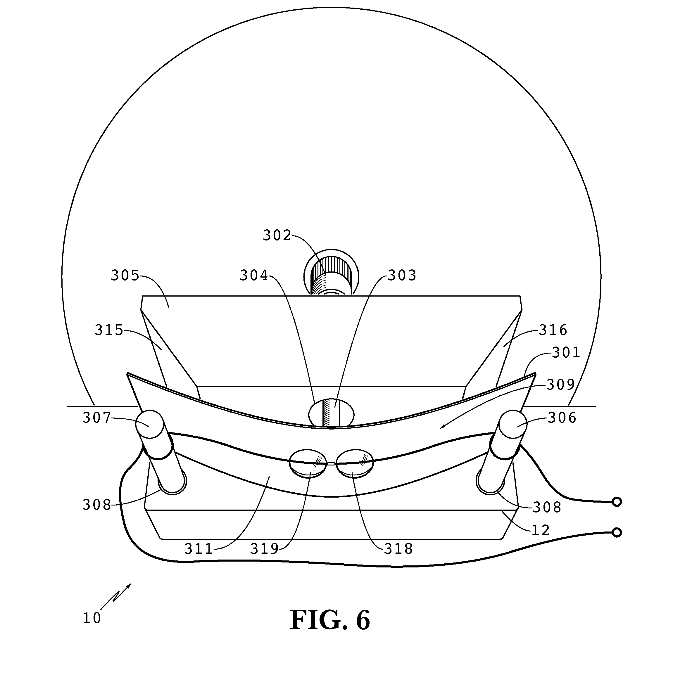
[0052]FIGS. 6 through 10 show the preferred assembly 10 that can be used in the experiment described herein. Of course, this assembly is not the only structure that embodies concepts described herein, as will become apparent to the person having ordinary skill from the description herein. Alternative structures and methods are described below, but others will become apparent to the person of ordinary skill from this description. The description of some alternatives does not imply that the description of alternatives herein is exhaustive.

[0053]The MCBJ assembly 10 preferably uses a spring steel sheet as a bending beam 301. Of course, any thin, flexible sheet can be substituted for spring steel, and includes plastic, aluminum and composites of glass fibers or carbon fibers in a flexible polymer matrix. The bending beam is preferably electrically non-conductive material...


PUM

PropertyMeasurementUnit
conduction measuringaaaaaaaaaa
lengthaaaaaaaaaa
currentaaaaaaaaaa

Abstract

A lab experiment device and method that demonstrate quantized conductance as a macroscopic gold wire is elongated and broken. The device utilizes a mechanically controlled break junction to demonstrate conductance quantization. A preferred assembly includes a rigid plate with a block to which a micrometer mounts. Spaced posts are mounted to the plate forming a gap between the posts and the block, and a flexible beam is seated against the posts with the anvil of the micrometer seated against the beam. A wire that is mounted to the beam elongates when the anvil forces the beam into a bending configuration. By passing current through the wire and detecting the voltage through a constriction formed in the wire, one can witness conductance quantization as the wire elongates at the constriction to form a conductor of one atom.

Description

CROSS-REFERENCES TO RELATED APPLICATIONS[0001]This application claims the benefit of U.S. Provisional Application No. 61 / 710,012 filed Oct. 5, 2012. This prior application is hereby incorporated by reference.STATEMENT REGARDING FEDERALLY-SPONSORED RESEARCH AND DEVELOPMENT[0002](Not Applicable)THE NAMES OF THE PARTIES TO A JOINT RESEARCH AGREEMENT[0003](Not Applicable)REFERENCE TO AN APPENDIX[0004](Not Applicable)BACKGROUND OF THE INVENTION[0005]The invention relates generally to equipment for scientific experiments, and more particularly to equipment for experimenting to demonstrate the properties of conductors.[0006]In recent decades there has been an enormous surge of interest in nanotechnology and nanoscience. This interest has been fueled by predictions that nanotechnology will have a significant and broad impact on many aspects of the future, including technology, food, medicine, and sustainable energy. Many universities in the U.S.A. and around the world started to establish p...

Claims


Application Information

Patent Timeline
Patent Type & Authority Applications(United States)
IPC IPC(8): G01N27/04
CPCG01N27/041B82Y30/00
Inventor EID, KHALID FATTHITOLLEY, ROBERT DOUGLAS
Owner MIAMI UNIVERSITY
Why Eureka
Try Eureka