Machine for the production of hollow glass

a hollow glass and forming machine technology, applied in glass blowing apparatus, glass shaping apparatus, applications, etc., can solve the problems of difficult to guarantee the accuracy of mechanical processing, the container has not the desired quality, and the punch is too much or too little into the blank, so as to facilitate the operation of the operator and reduce the space inside the section.

Active Publication Date: 2014-04-24
BOTTERO SPA
View PDF6 Cites 6 Cited by
  • Summary
  • Abstract
  • Description
  • Claims
  • Application Information

AI Technical Summary

Benefits of technology

[0030]As it will be better seen in the description below, this solution allows the driving units to be installed inside the section in a simple and compact manner.
[0031]Preferably, the base plate provides centering and fixing means for the driving units, particularly pegs, fixing threads and posit

Problems solved by technology

A wrong adjustment of the base plate, causes the punch to enter too much or too little into the blank mold, and as a consequence the container has not the desired quality.
Therefore the male mechanism is positioned by using two elements fixed to the lower plate and to the upper plate of the housing respectively, which are two separated components, or they are part of the single h

Method used


Image

  • Machine for the production of hollow glass
  • Machine for the production of hollow glass
  • Machine for the production of hollow glass

Examples


Embodiment Construction

[0051]While the invention is susceptible of various modifications and alternative forms, some preferred embodiments are shown in the drawings and will be described below in detail. It should be understood, however, that there is no intention to limit the invention to the specific embodiment disclosed, but, on the contrary, the intention of the invention is to cover all modifications, alternative forms, and equivalents falling within the scope of the invention as defined in the claims.

[0052]In the description below and in the figures, like elements are denoted by like reference numerals. The use of “for example”, “etc.”, “or” indicates non-exclusive alternatives without limitation unless otherwise noted. The use of “including” means “including, but not limited to,” unless otherwise noted.

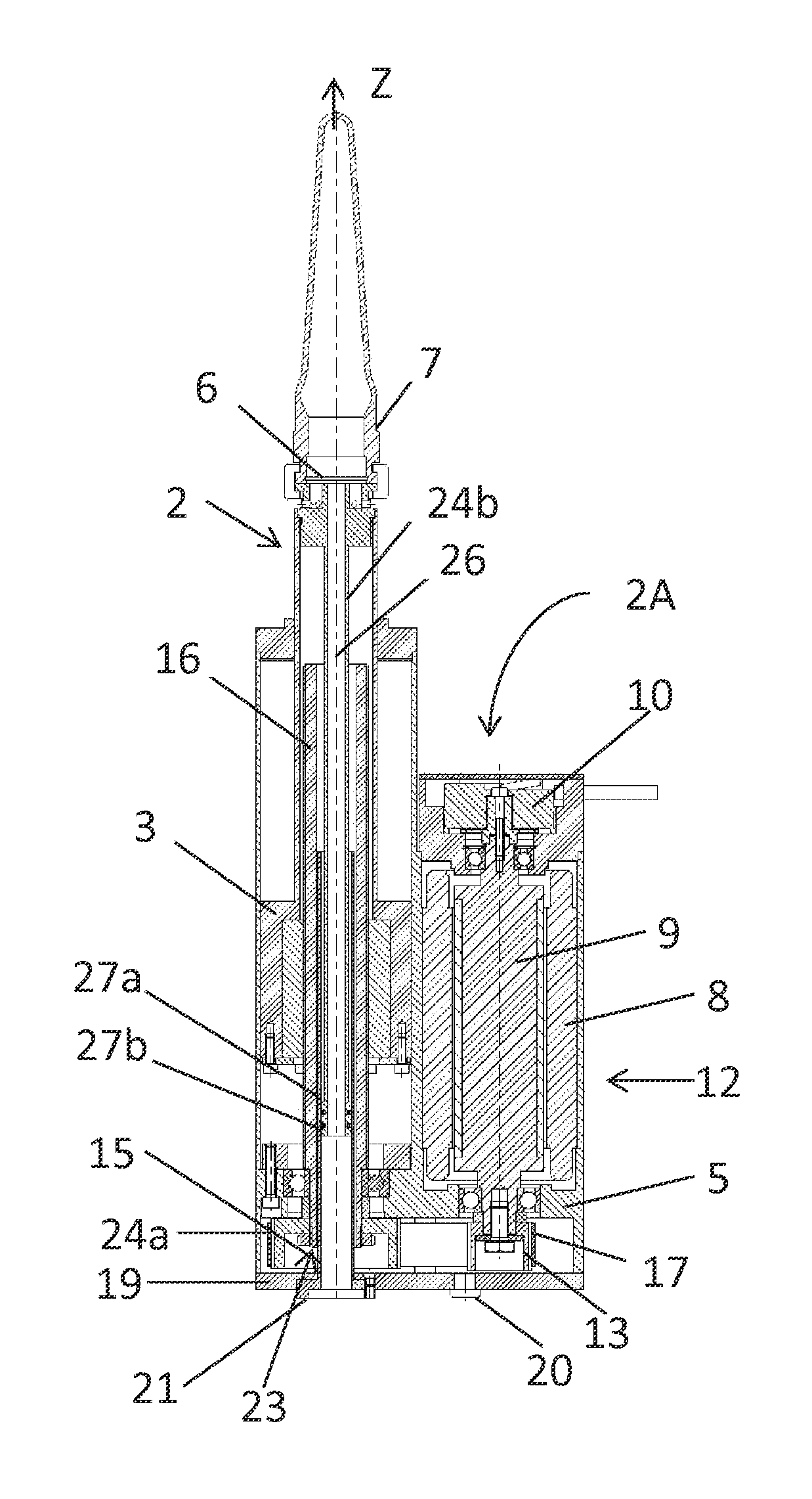
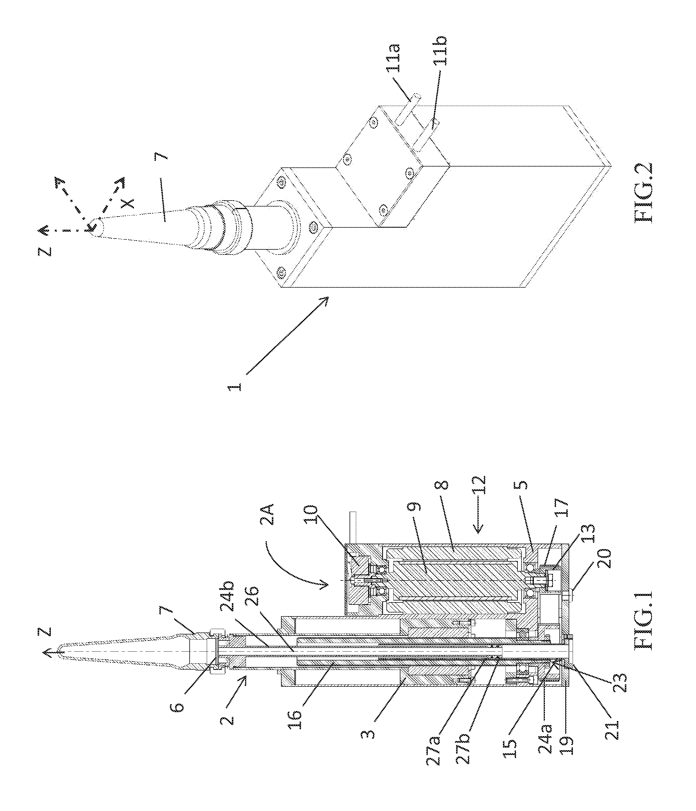
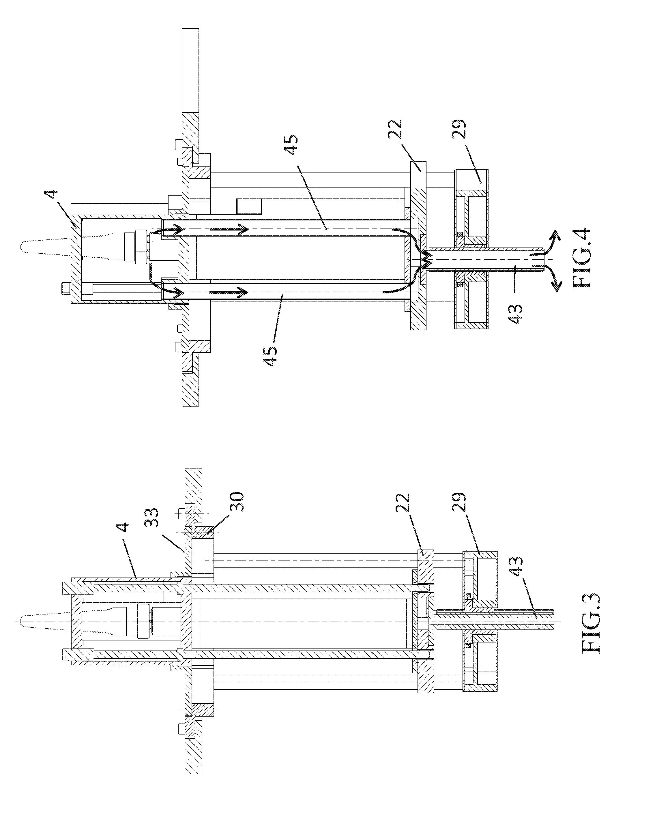
[0053]The term “blank station” of a hollow glass forming machine means the assembly of components allowing the blank (parison) of a hollow glass container to be made. Such station therefore comprises...


PUM

PropertyMeasurementUnit
Fractionaaaaaaaaaa
Angleaaaaaaaaaa
Lengthaaaaaaaaaa

Abstract

The present invention relates to a system for aligning and positioning a male mechanism—pneumatic or servo-electric—to be used at the blank station side of a section of a hollow glass forming machine. The system comprises a mechanism, comprising at least one plunger or a driving unit driven by a servomotor, a guide flange composed of an internal flange for retaining the mechanism in position, and an external flange.
The system further comprises a base plate for supporting the mechanism. The plate is mounted on at least one guide bar, rigidly fixed to the resting face of the external flange and intended to allow the base plate to slide along a sliding direction substantially orthogonal to the plane wherein the external flange lies. The base plate rests on a height adjustment group, suspended to said upper plane and intended to move the plate along the guide.

Description

TECHNICAL FIELD[0001]The present invention relates to the field of hollow glass forming machines and more in detail to the field of machines with individual sections, also known as “individual section machines” or more shortly defined by their acronym IS (Individual Section).[0002]More in detail, the present invention relates to a system and a method for aligning and positioning the male mechanism in a section of a IS machine.[0003]The invention further relates to methods for arranging one or more driving units of a servo-electric male mechanism, namely driven by servomotors, such to facilitate the driving units to be mounted from the top inside the section.PRIOR ART[0004]It is known that hollow glass forming machines can operate by a production technology of the “blow-blow” or “press-blow” type, the difference being in the blank molding process of the glass container formed by the machine.[0005]In IS machines operating with a “press-blow” process, a gob of molten glass is inserted ...

Claims


Application Information

Patent Timeline
IPC IPC(8): C03B11/16C03B11/10
CPCC03B11/10C03B11/16C03B9/1932C03B9/1938Y10T29/49716
Inventor KUZ, ZDENKOBAROLO, MAURIZIO
Owner BOTTERO SPA
Why Eureka
Try Eureka