
Method of operating an internal combustion engine

a technology of internal combustion engine and internal combustion chamber, which is applied in the direction of combustion engine, machine/engine, electric control, etc., can solve the problems of different torques to be generated between cylinders, performance, or more specifically timing, and the quantity of fuel delivered by the injectors diverging beyond acceptable limits,

Active Publication Date: 2014-04-24
DELPHI INT OPERATIONS LUXEMBOURG S A R L +1
View PDF17 Cites 16 Cited by
  • Summary
  • Abstract
  • Description
  • Claims
  • Application Information

AI Technical Summary

Benefits of technology

The patent is about a method for measuring fuel quantity in an engine and using the information to adjust the amount of fuel injected during combustion. The method includes baseline pressure measurements before and after a learning injection to account for heat loss. These measurements are important for accurately computing the amount of fuel injected and the amount of heat released during combustion. The method also uses offset mapping and interpolation to quickly converge towards the target. The technical effects of this method include improved fuel injection control and more accurate data for combustion research.

Problems solved by technology

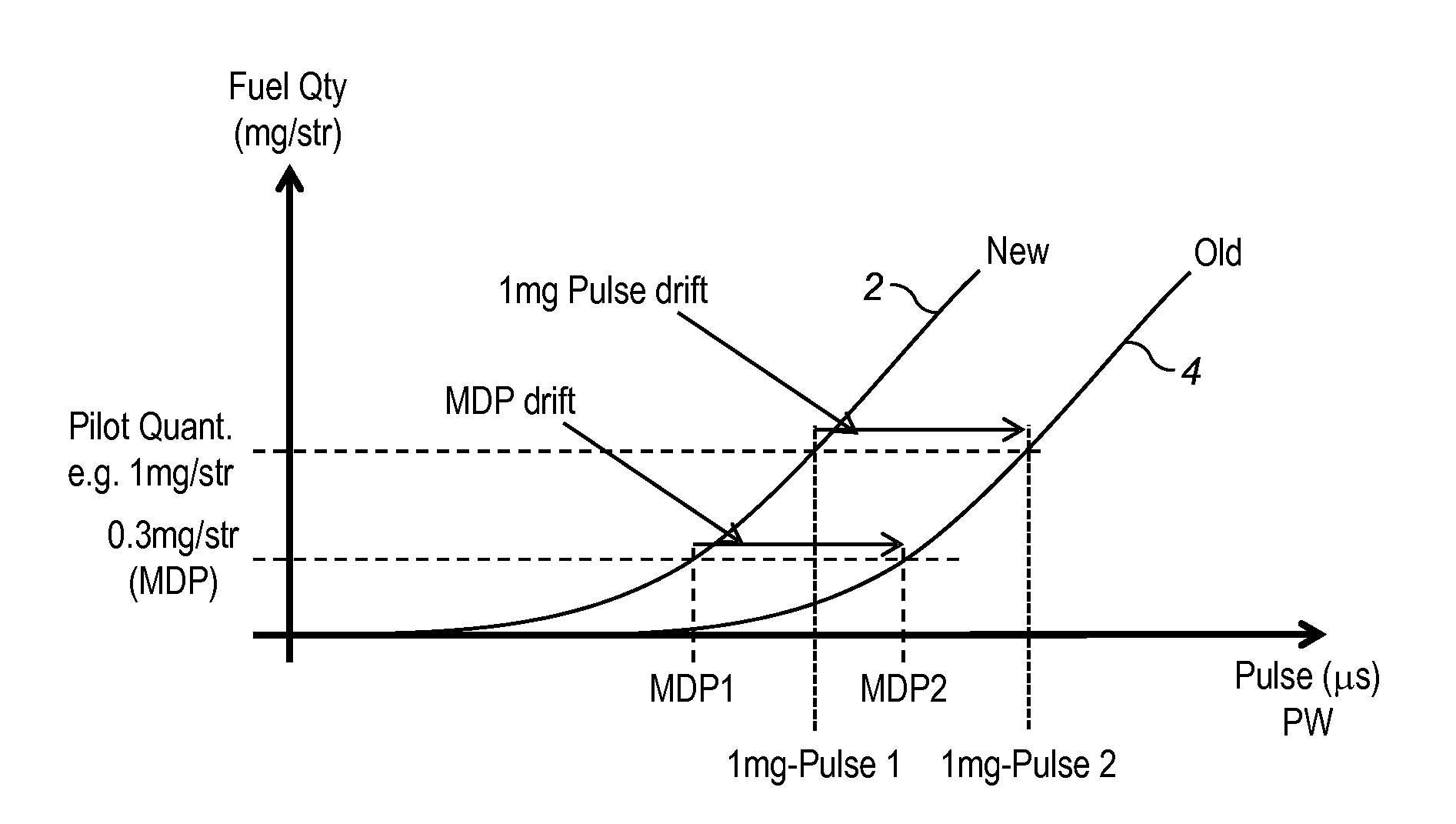
Indeed, it is well known that problems arise when the performance, or more particularly the timing, and the quantity of fuel delivered by the injectors diverge beyond acceptable limits.
For example, injector performance deviation or variability will cause different torques to be generated between cylinders due to unequal fuel quantities being injected, or from the relative timing of such fuel injection.
It may be further noted that the problem of injector variability is particularly acute when injecting small fuel quantities.
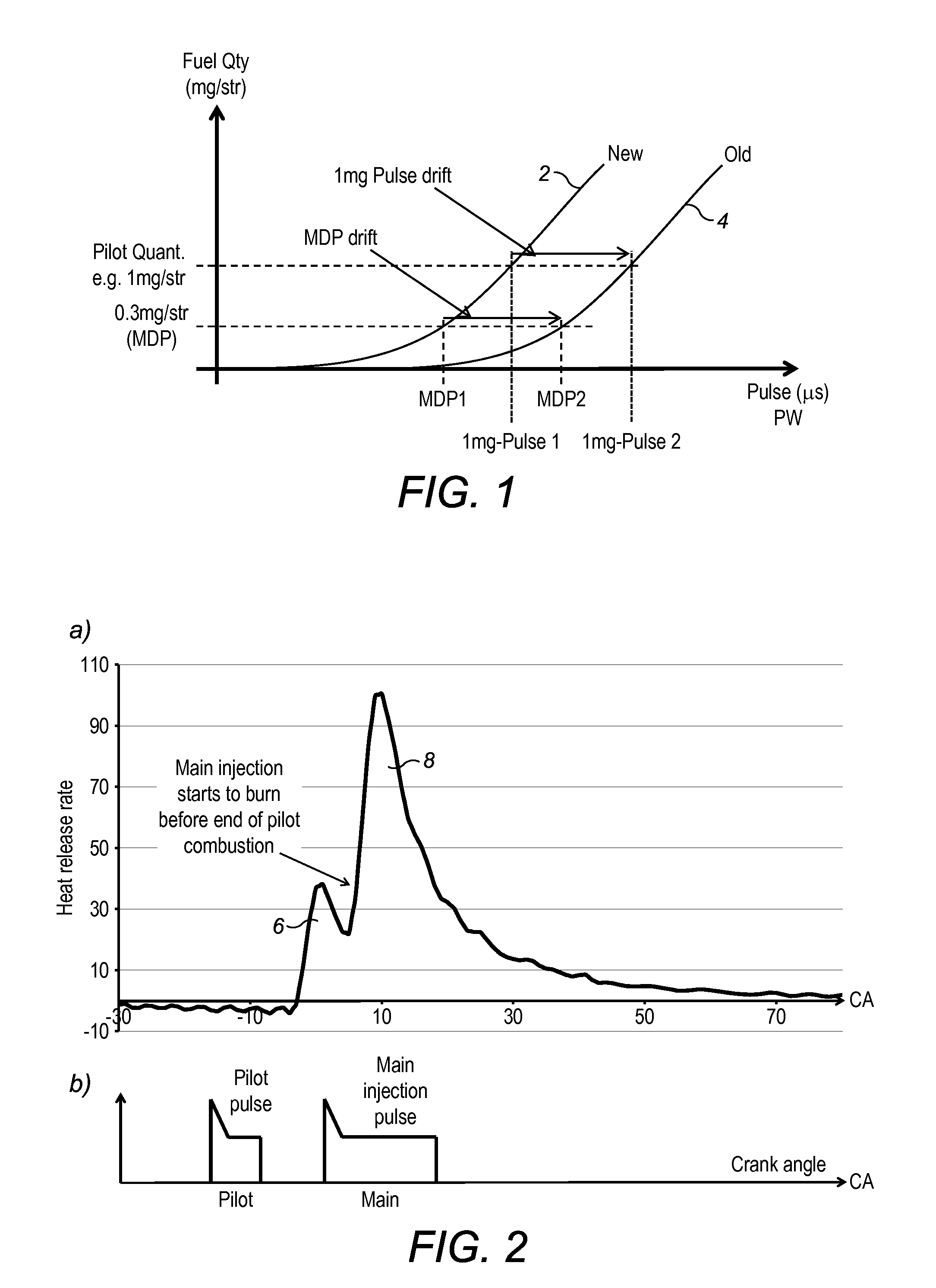
However, the approach described in US 2009 / 0292447 appears to be difficult to implement in practice, in particular where modern emission reduction strategies seek to minimize the time intervals between injected amounts within a same combustion cycle.
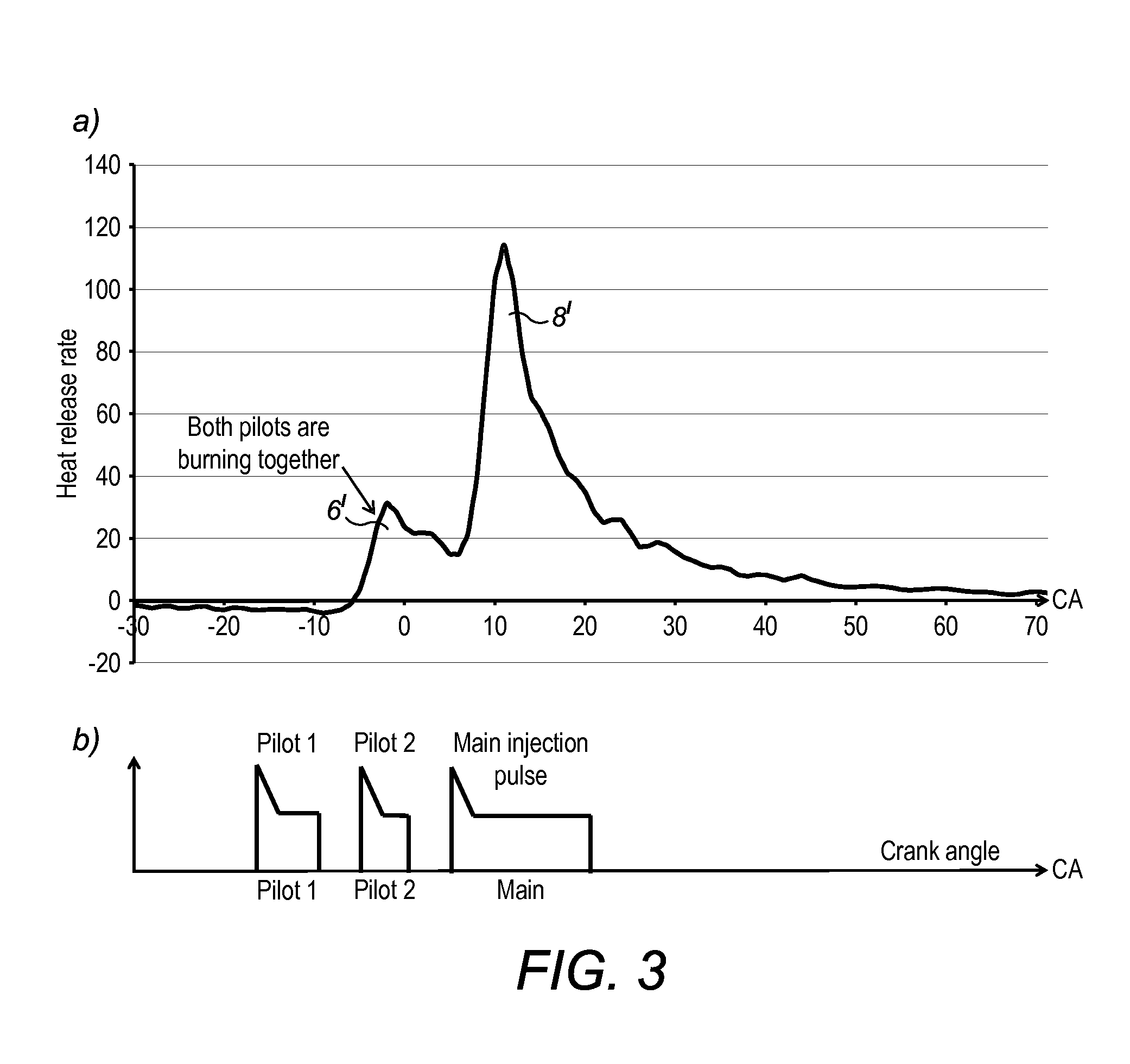
Accordingly, when there are e.g. 3 injections (two pilots and one main) within an engine combustion cycle, the respective combustion events tend to overlap and determining the pilot contribution is difficult.

Method used


Image

  • Method of operating an internal combustion engine
  • Method of operating an internal combustion engine
  • Method of operating an internal combustion engine

Examples


Embodiment Construction

[0045]The present method will now be described, by way of example, with respect to the operation of a diesel reciprocating engine (4-stroke internal combustion engine) of a four-wheeled vehicle. As it is well known, such engine may typically comprise a cylinder block with one or more cylinders, each having a piston slideably received therein. The pistons are operatively connected to a common output shaft formed by a crankshaft equipped with a flywheel. Fuel is introduced into the combustion chambers of the respective cylinders to be combusted and thus reciprocate the four pistons in sequence to thereby rotate the crankshaft. Therefore, the engine may be equipped with a common rail fuel injection system.

[0046]Each of the combustion chambers communicates with an intake manifold and an exhaust manifold by means of intake and exhaust valves, respectively, that are driven by a camshaft synchronized with the crankshaft.

[0047]The intake manifold system, through which fresh air is admitted ...


PUM


Abstract

A method of operating an internal combustion engine, wherein the engine is operated in an injector learning mode in which an injection parameter associated with a nominal fuel quantity of a pilot injection is learned, includes performing a learning pilot injection based on a candidate value for the injection parameter to influence injection of the nominal fuel quantity and determining a parameter indicative of the actually injected fuel quantity based on the in-cylinder pressure during combustion of the learning pilot injection. The learning pilot injection is operated at an early timing such that combustion thereof complete occurs within a learning window positioned before combustion TDC and before the next combustion starts. The pressure is measured over the learning window, so that the determination of the parameter indicative of the actually injected fuel quantity takes into account essentially the entire combustion event of the learning pilot injection.

Description

CROSS REFERENCE TO RELATED APPLICATIONS[0001]This application claims the benefit of European Patent Application No. 12189607.0 filed on 23 Oct. 2012, the entire disclosure of which is hereby incorporated herein by reference.FIELD OF THE INVENTION[0002]The present invention generally relates to the operation of internal combustion engines and in particular to fuel injection in such engines. More specifically, the present invention concerns the learning of pilot fuel injections.BACKGROUND OF THE INVENTION[0003]The contemporary design of internal combustion engines must cope with the increasingly stringent regulations on pollutant emissions. Accordingly, automotive engineers strive for designing engines with low fuel consumption and low emission of pollutants, which implies including electronic devices capable of monitoring the combustion performance and emissions in the exhaust gases.[0004]A proper operation of a fuel-injected engine requires that the fuel injectors and their controll...

Claims


Application Information

Patent Timeline
Patent Type & Authority Applications(United States)
IPC IPC(8): F02D41/00
CPCF02D41/0047F02D41/402F02D41/403Y02T10/40
Inventor ALLEZY, PIERREGUERRASSI, NOUREDDINEGOY, MATTHIEUGHIRLANDA, ALESSIO
Owner DELPHI INT OPERATIONS LUXEMBOURG S A R L
Learn More