
Energy management system for auxiliary power source

a technology of energy management system and auxiliary power source, applied in the direction of dc source parallel operation, emergency power supply arrangement, sustainable building, etc., can solve the problems of personal injury and/or damage to utility equipment (transformers, etc., and achieve efficient resolution, optimize the use of generator power source, and monitor and balance

Inactive Publication Date: 2014-04-24
BALDASSARRE JOHN +2
View PDF0 Cites 40 Cited by
  • Summary
  • Abstract
  • Description
  • Claims
  • Application Information

AI Technical Summary

Benefits of technology

The present invention is a system that can monitor the power output of a generator and automatically remove unnecessary loads to prevent the generator from overloading. The system allows users to change the priority of loads in real-time and restore them later. The system can also evaluate loads based on their history and current power demand to ensure optimal power distribution. The user-defined overlay allows for real-time balancing of loads without the need for predetermined priority lists or preset timers. This system provides an efficient and flexible solution for managing power distribution in emergency situations.

Problems solved by technology

However, one cannot simply leave the back-up generator permanently connected, in parallel with the utility power, to the residential electrical circuits, nor can one simply connect and power up a back-up generator, without first disconnecting the residential circuits from the power lines coming in from the utility.
The reason for this is the possibility that some of the current generated by the back-up generator may inadvertently be back fed into the utility power lines, which may lead to personal injury and / or damage to utility equipment (transformers, etc.).
In a typical situation, utility power fails or falls drastically.
This may be undesirable, in that some appliances (e.g., refrigerator or freezer, sump pump, pool heater, etc.) should not go without power for extended periods of time.
If a homeowner is absent for an extended period of time (e.g. more than an hour or two), continued power outages may cause potentially serious damage or injury to equipment, property, pets, etc.
While known electrical systems are able to shed and restore loads according to a user defined predetermined priority list for utility power curtailment and / or peak demand limiting, there does not exist a system that sheds and restores loads coupled to an auxiliary or generator source during an interruption or power failure of the utility power source.
Moreover, there does not exist a system that allows the user to update and / or change the priorities of the loads in real-time, as the needs of the user may vary.
Additionally, known systems for utility power curtailment or management of an auxiliary power source do not allow the user to continuously update the priorities of particular electrical loads in real-time, whereby the supply of power to the particular electrical loads is required throughout the completion of a process.
Moreover, known systems for utility power curtailment or management of an auxiliary power source are unable to vary the priorities of the loads according to the user's past history of usage of devices or preferred priority at particular times of year (e.g., the user may tend to utilize different devices more during the summer than during the winter) or even particular times throughout the day (e.g., the user may tend to utilize different devices more during the afternoon than during the evening), whereby these particular preferences can be stored by the system.

Method used


Image

  • Energy management system for auxiliary power source
  • Energy management system for auxiliary power source
  • Energy management system for auxiliary power source

Examples


Embodiment Construction

[0046]Detailed illustrative embodiments of the present invention are disclosed herein. However, techniques, systems, and operating structures in accordance with the present invention may be embodied in a wide variety of forms and modes, some of which may be quite different from those in the disclosed embodiments. Consequently, the specific structural and functional details disclosed herein are merely representative, yet in that regard, they are deemed to afford the best embodiments for the purposes of disclosure and to provide a basis for the claims herein, which define the scope of the present invention. The following presents a detailed description of preferred embodiments (as well as some alternative embodiments) of the present invention.

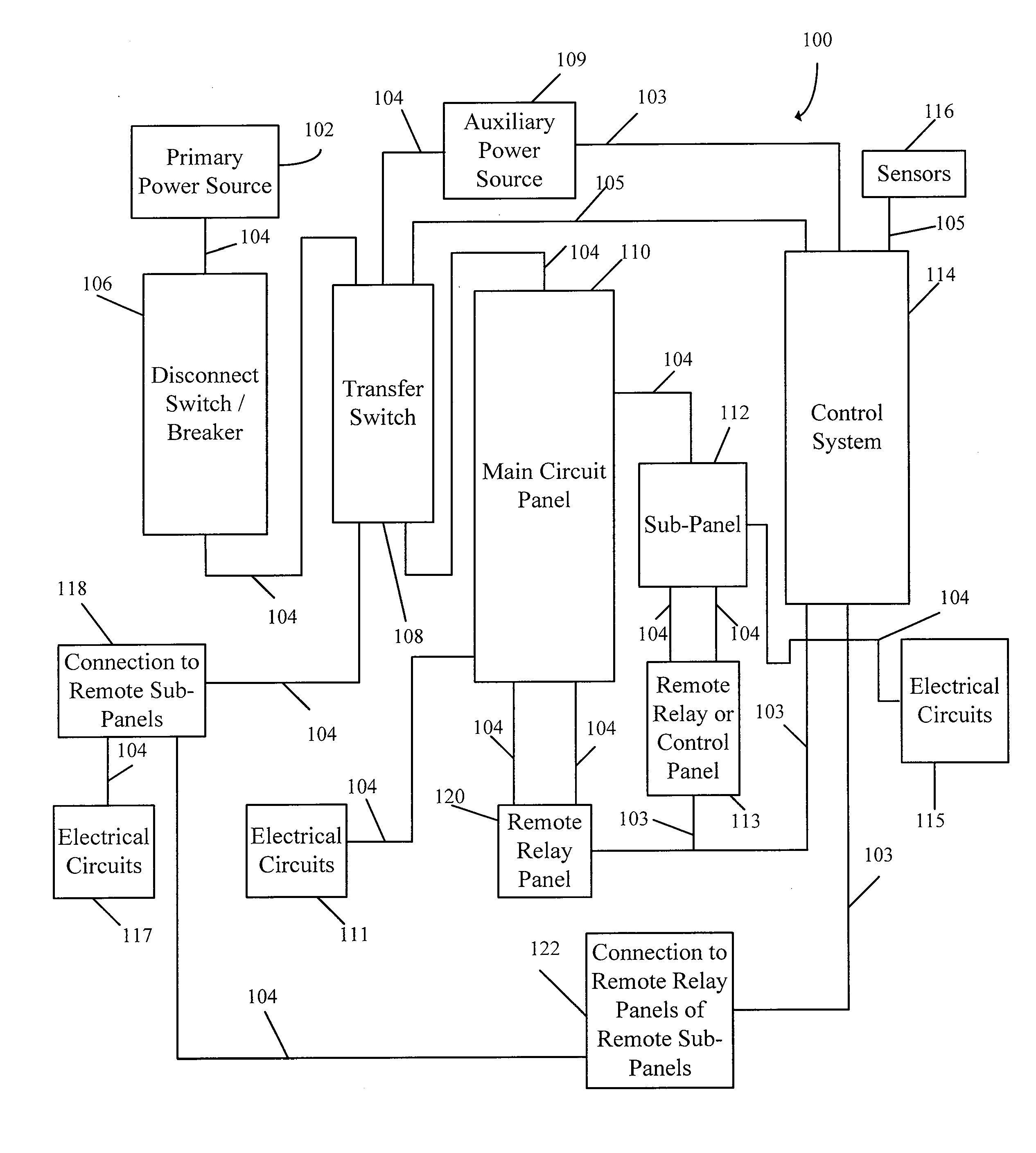
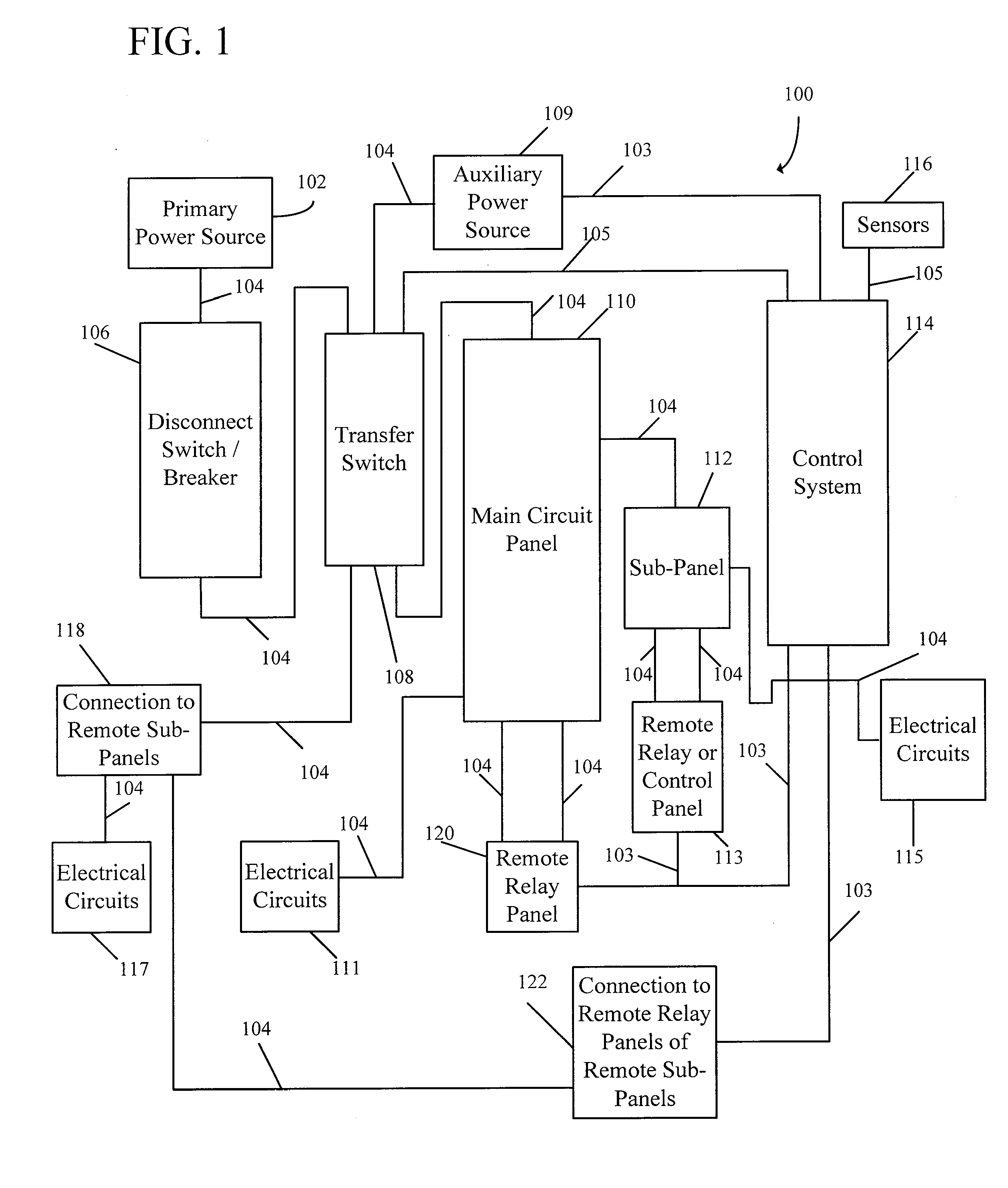
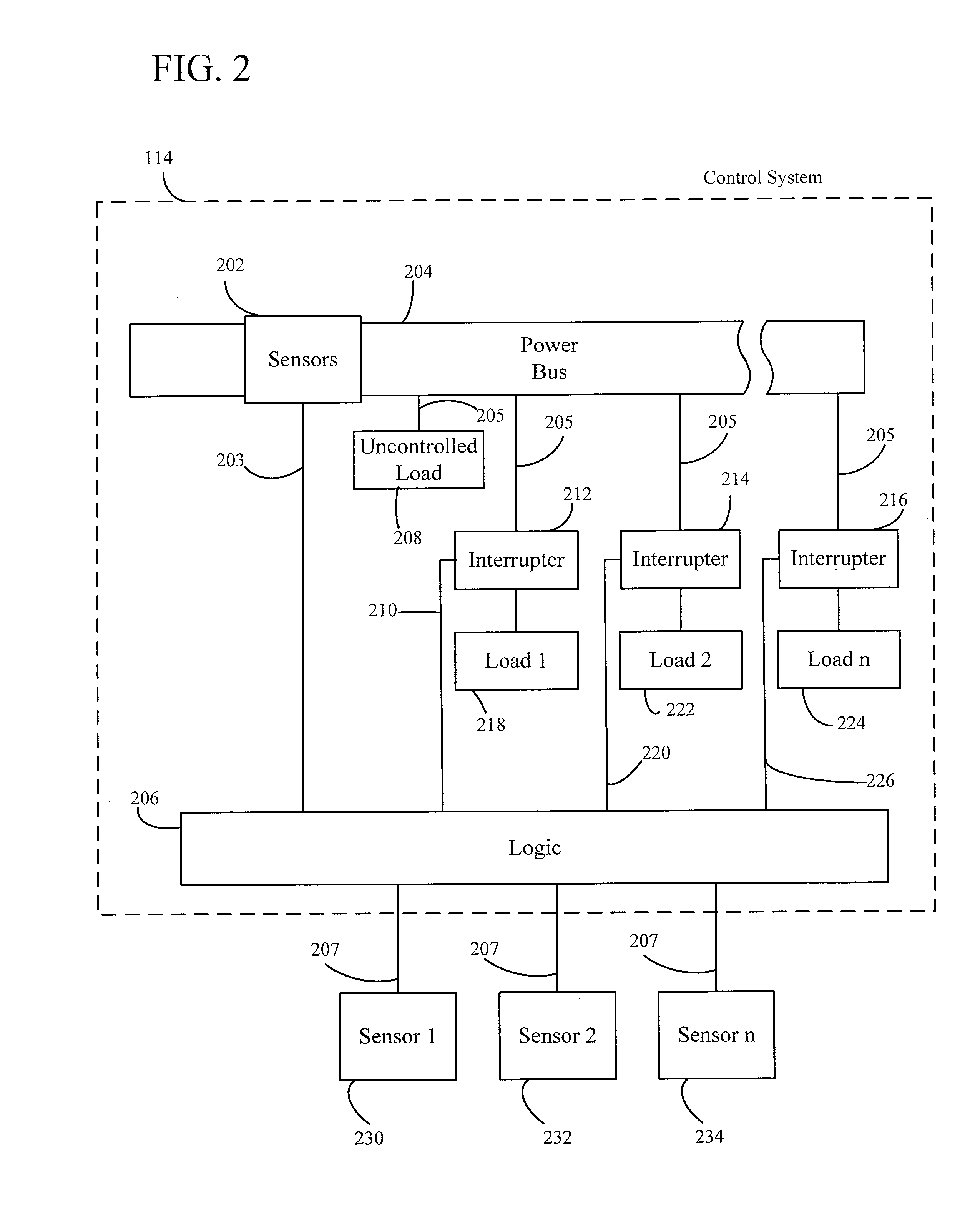
[0047]A further understanding of the present invention can be obtained by reference to a preferred embodiment. Although the illustrated embodiment is merely exemplary of systems for carrying out the present invention, both the organization and me...


PUM


Abstract

A control system is provided for controlling a load powered by an auxiliary power source during an interruption in the utility power source and / or during a power failure. The control system of the present invention provides power to essential loads in a dwelling as predetermined by a user and / or per the user's real-time instructions as the needs of the user may change. Additionally, the control system of the present invention automatically controls non-essential loads in order to maintain the auxiliary power load below the maximum threshold. Furthermore, the control system of the present invention allows the user to manually override all the controlled loads in an emergency or when the needs of the user change. Additionally, the control system of the present invention allows outside triggers to change the priority of the loads in real-time and can automatically change the priority due to predetermined tasks already running.

Description

CROSS-REFERENCE TO RELATED APPLICATIONS[0001]This application claims priority to application Ser. No. 61 / 135,952, filed Jul. 24, 2008.FIELD OF THE INVENTION[0002]The present invention generally relates to the technical field of energy management systems, implemented for use with portable or stationary auxiliary power sources such as electric generators, solar power sources, nuclear power sources, etc. More specifically, the present invention relates to a control system and automatic transfer switch apparatus adapted for controlling the total electrical energy consumption of a circuit or group of circuits, which includes a plurality of loads having different current demands, whereby a user controls the power supplied by the auxiliary power source to electrical loads in real-time.BACKGROUND OF THE INVENTION[0003]Transfer switches, for use in association with portable or stand-alone electrical generators, are known in the prior art.[0004]A private residence, for example, may normally r...

Claims


Application Information

Patent Timeline
Patent Type & Authority Applications(United States)
IPC IPC(8): H02J9/06
CPCH02J9/06H02J9/002H02J2310/16Y02B10/70
Inventor BALDASSARRE, JOHNBALDASSARRE, FRANKKESELMAN, ISAAC
Owner BALDASSARRE JOHN
Learn More