
System of computing surface reconstruction, in-plane and out-of-plane displacements and strain distribution

a computing surface and displacement technology, applied in the field of computing surface reconstruction, can solve the problems of significant image calibration error, limited application of the interferometer to other purposes of measurement, and inability to accurately detect the position of the test object, so as to reduce the complexity and error of scanning the test object, and increase the measurement range

Inactive Publication Date: 2014-04-24
NAT APPLIED RES LAB
View PDF5 Cites 8 Cited by
  • Summary
  • Abstract
  • Description
  • Claims
  • Application Information

AI Technical Summary

Benefits of technology

The present invention utilizes an optical switching element to analyze images of a testing object to measure topography, displacement, and strain distribution on the surface. This increases the measurement range with image registration. Compared to conventional technology, the present invention reduces complexity and error by not moving the image capturing device or test object. This allows for three-dimensional coordinates of the testing surface to be measured without needing to move the equipment.

Problems solved by technology

However the fixed integration in architecture of the hardware of the interferometer limits its applications to other purposes of measurements.
If the distance between the test object to be shot and the capture device is not constant, then measurement errors occur and the accuracy will be affected, which will need three-dimensional digital measurement technology.
However, in the above three-dimensional digital image measurement, the two image capture devices used to capture the images at two different locations may have different mechanical and optical properties, and the related position between the two image capture devices is not constant, resulting in significant error in image calibration and adversely affecting image accuracy.
Therefore, it is quite difficult for image calibration in the three-dimensional coordinate measurement in the prior art which uses the two image capture devices.

Method used


Image

  • System of computing surface reconstruction, in-plane and out-of-plane displacements and strain distribution
  • System of computing surface reconstruction, in-plane and out-of-plane displacements and strain distribution
  • System of computing surface reconstruction, in-plane and out-of-plane displacements and strain distribution

Examples


Embodiment Construction

[0039]The aforementioned illustrations and following detailed descriptions are exemplary for the purpose of further explaining the scope of the present invention. Other objectives and advantages related to the present invention will be illustrated in the subsequent descriptions and appended tables.

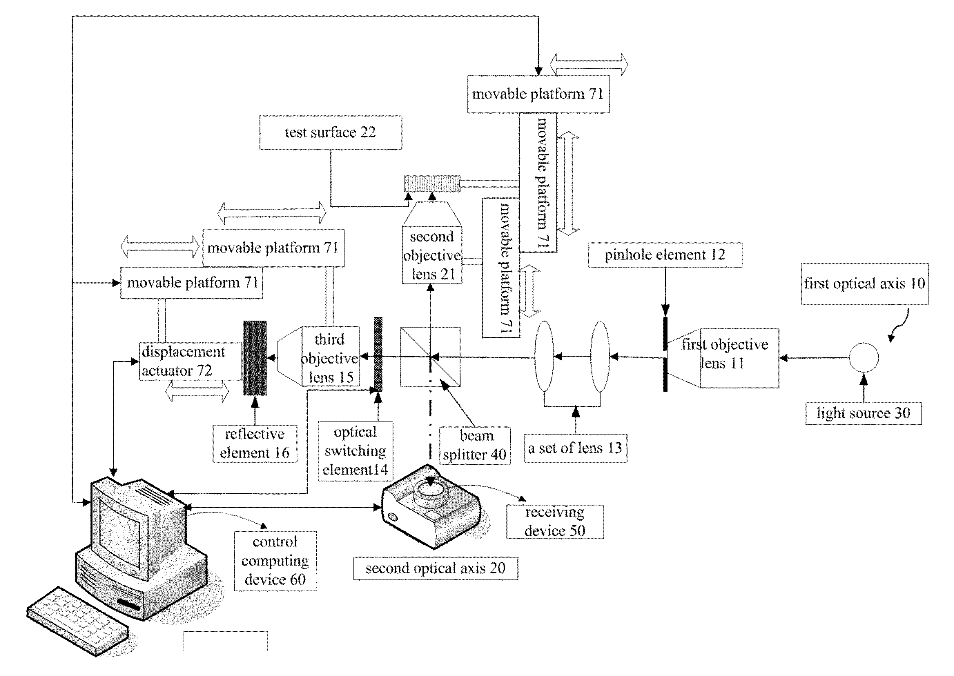
[0040]FIG. 5 is a schematic architecture of a system of surface reconstruction, in-plane and out-of-plane displacements and strain distribution according to one embodiment of the invention.

[0041]Referring to FIG. 5, the system of surface reconstruction, in-plane and out-of-plane displacements and strain distribution according to the invention includes a light source 30, a first objective lens 11, a pinhole element 12, a set of lens 13, a beam splitter 40, a second objective lens 21, an optical switching element 14, a third objective lens 15, a reflective element 16, a receiving device 50 and a control computing device 60.

[0042]The light source 30 is set out of the first objective lens 11 a...


PUM


Abstract

A system of computing surface reconstruction, in-plane and out-of-plane displacements and strain distribution utilizes the optical switching element to switch the reference beam to analyze the images of the test object before and after deformation, to measure the topography, in-plane and out-of-plane displacements and surface two-dimensional strain distribution on the test surface of the test object, and thus to increase the measurement range on the test surface of the test object with the use of image registration. Thereby, the complexity and error of scanning the test object can be reduced. Such a system need not to move the image capturing device or test object to generate relative displacement for reaching the measurement effect of the test surface of the test object in three-dimensional coordinates.

Description

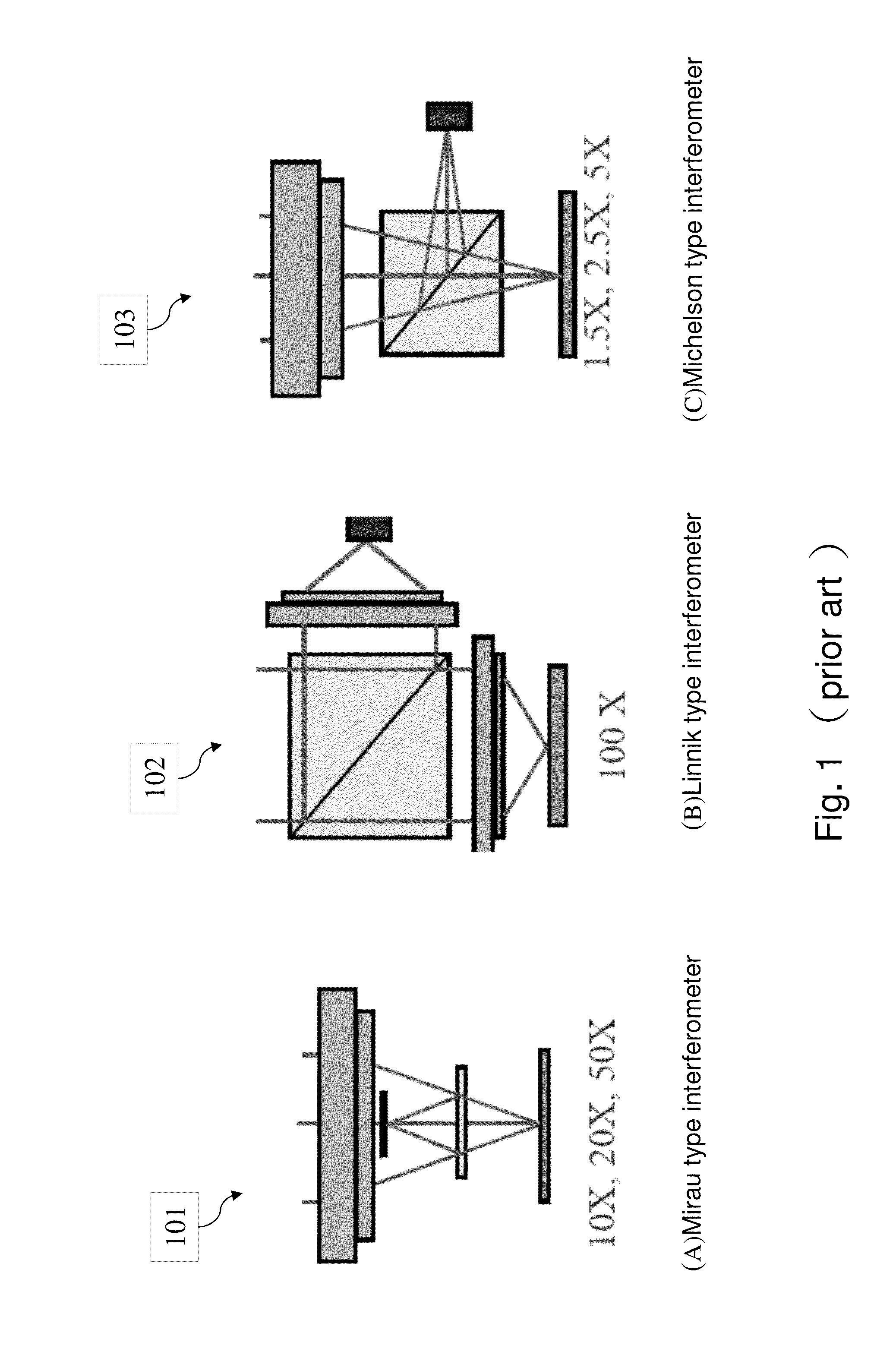
BACKGROUND OF THE INVENTION[0001]1. Field of the Invention[0002]The present invention relates to a system of computing surface reconstruction, in-plane and out-of-plane displacements and strain distribution on a test surface of a test object before and after the stress is applied.[0003]2. Description of Related Art[0004]The interferometer has been widely used in surface topography measurement, applied to semiconductor wafers, liquid crystal display glass panels in a manner of non-contact measurement. Types of setting an optical path of the interferometer mainly include Mirau, Linnik, and Michelson. References may be made to FIG. 1A, FIG. 1B, and FIG. 1C. FIG. 1A is a schematic architecture of a conventional Mirau type interferometer. FIG. 1B is a schematic architecture of a conventional Linnik type interferometer. FIG. 1C is a schematic architecture of a conventional Michelson type interferometer.[0005]In the Mirau type interferometer 101 and the Michelson type interferometer 103, t...

Claims


Application Information

Patent Timeline
IPC IPC(8): G01B11/24
CPCG01B9/0203G01B9/02087G01B11/161
Inventor SHEN, MING-HSINGHUANG, CHI-HUNGWANG, WEI-CHUNGCHEN, YUNG-HSIANG
Owner NAT APPLIED RES LAB
Learn More