Radio Wave Propagation Environment Measuring Apparatus, Radio Network Construction System, and Method For Measuring Radio Wave Propagation Environment
a radio network and environment technology, applied in the direction of receiving monitoring, transmission monitoring, instruments, etc., can solve the problems of reducing the reliability of one path, requiring high reliability in the application of wireless real-time communication to the industry field, and requiring the treatment of failures in wireless networks. achieve the effect of easy to obtain
- Summary
- Abstract
- Description
- Claims
- Application Information
AI Technical Summary
Benefits of technology
Problems solved by technology
Method used
Image
Examples
first embodiment
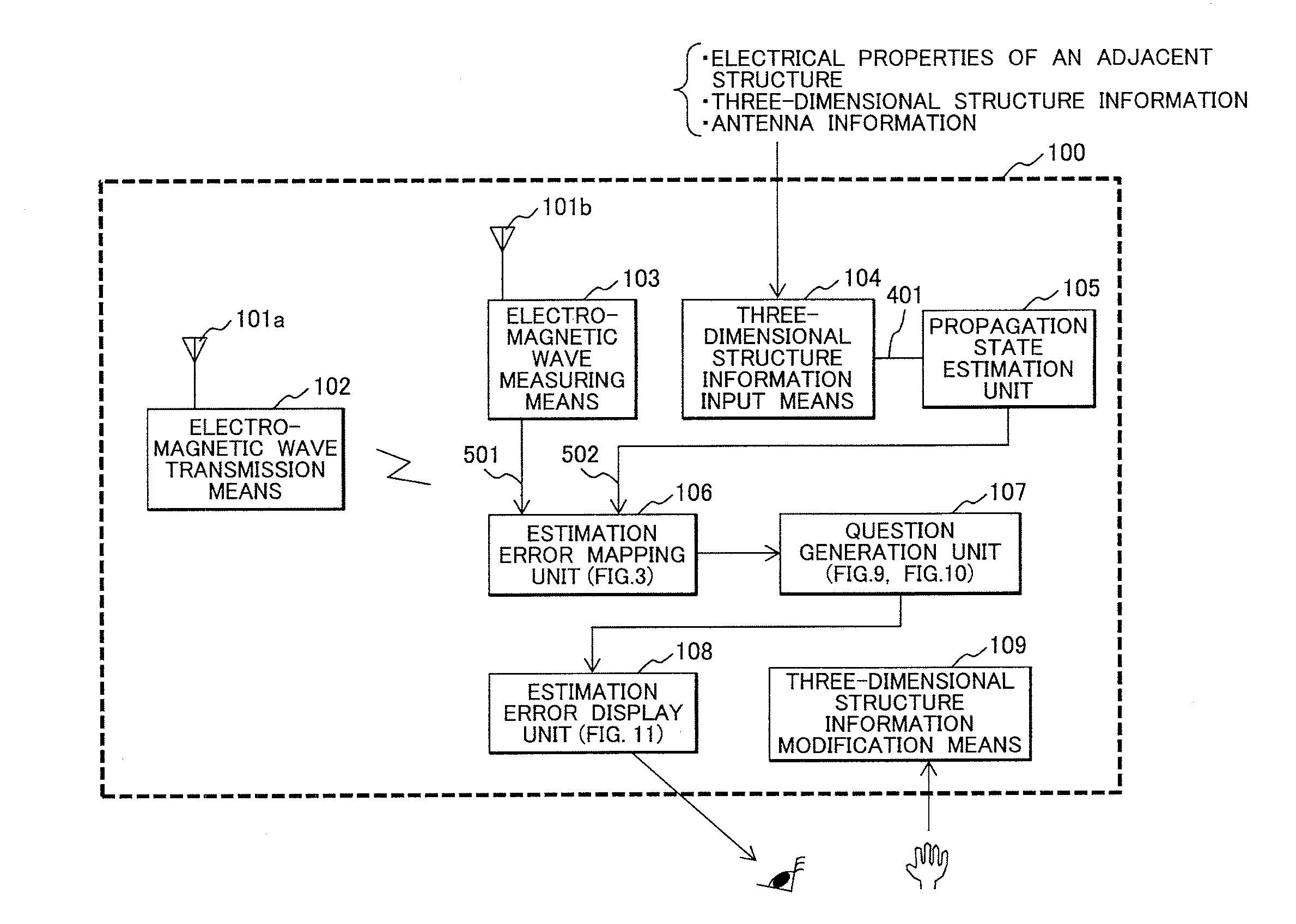
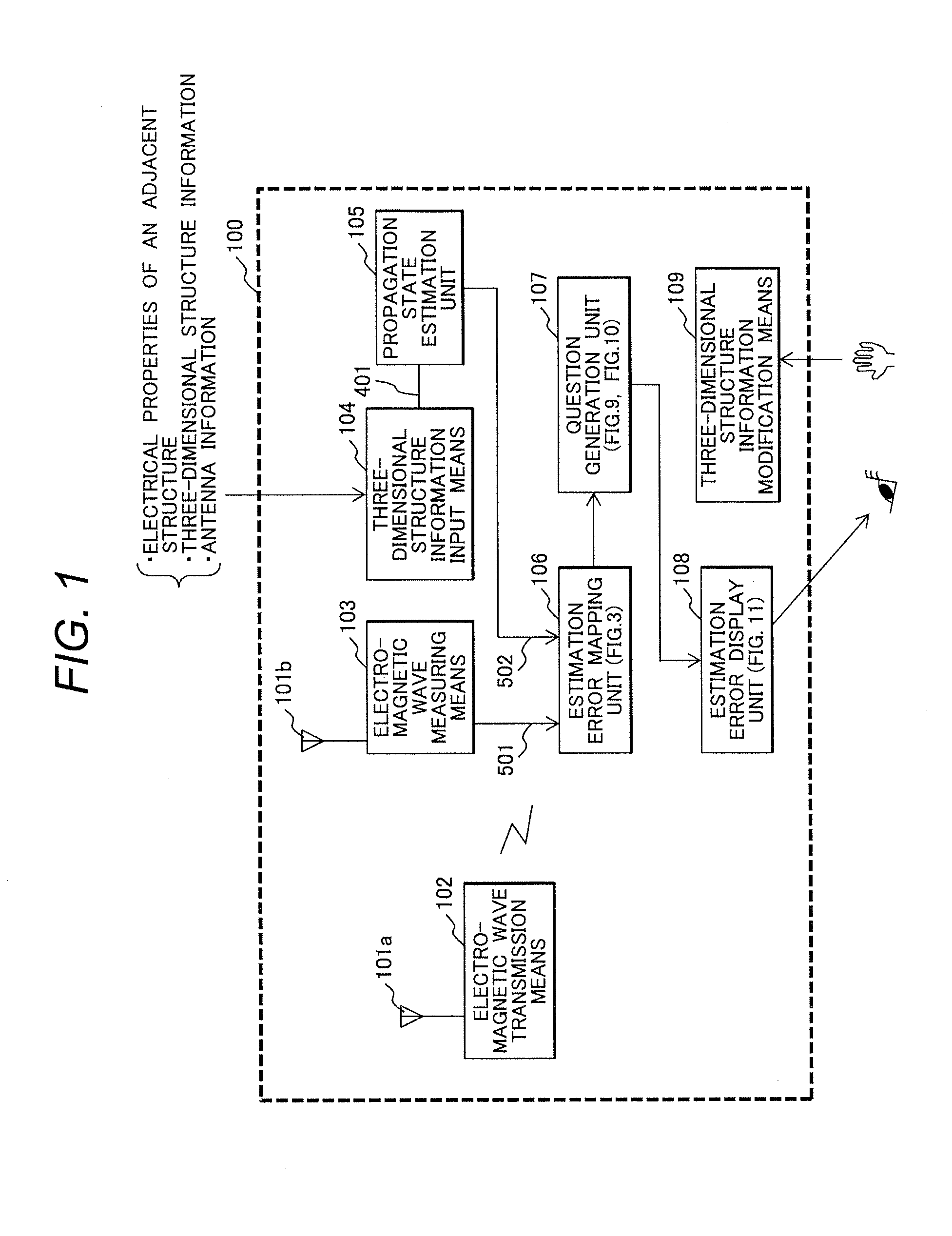
[0039]FIG. 1 is a diagram showing an example configuration of a radio wave propagation environment measuring apparatus 100 according to a first embodiment of the present invention. The radio wave propagation environment measuring apparatus 100 includes an electromagnetic wave transmission means 102 including a transmission antenna 101a, an electromagnetic wave measuring means 103 including a receiving antenna 101b, a three-dimensional structure information input means 104, a propagation state estimation unit 105, an estimation error mapping unit 106, a question generation unit 107, an estimation error display unit 108, and a three-dimensional structure information modification means 109.
[0040]Before describing the configuration of FIG. 1 in detail, the functions of the radio wave propagation environment measuring apparatus 100 will be outlined. One input, 501, provided to the estimation error mapping unit 106 is actually measured data (measured value) from the electromagnetic wave m...
second embodiment
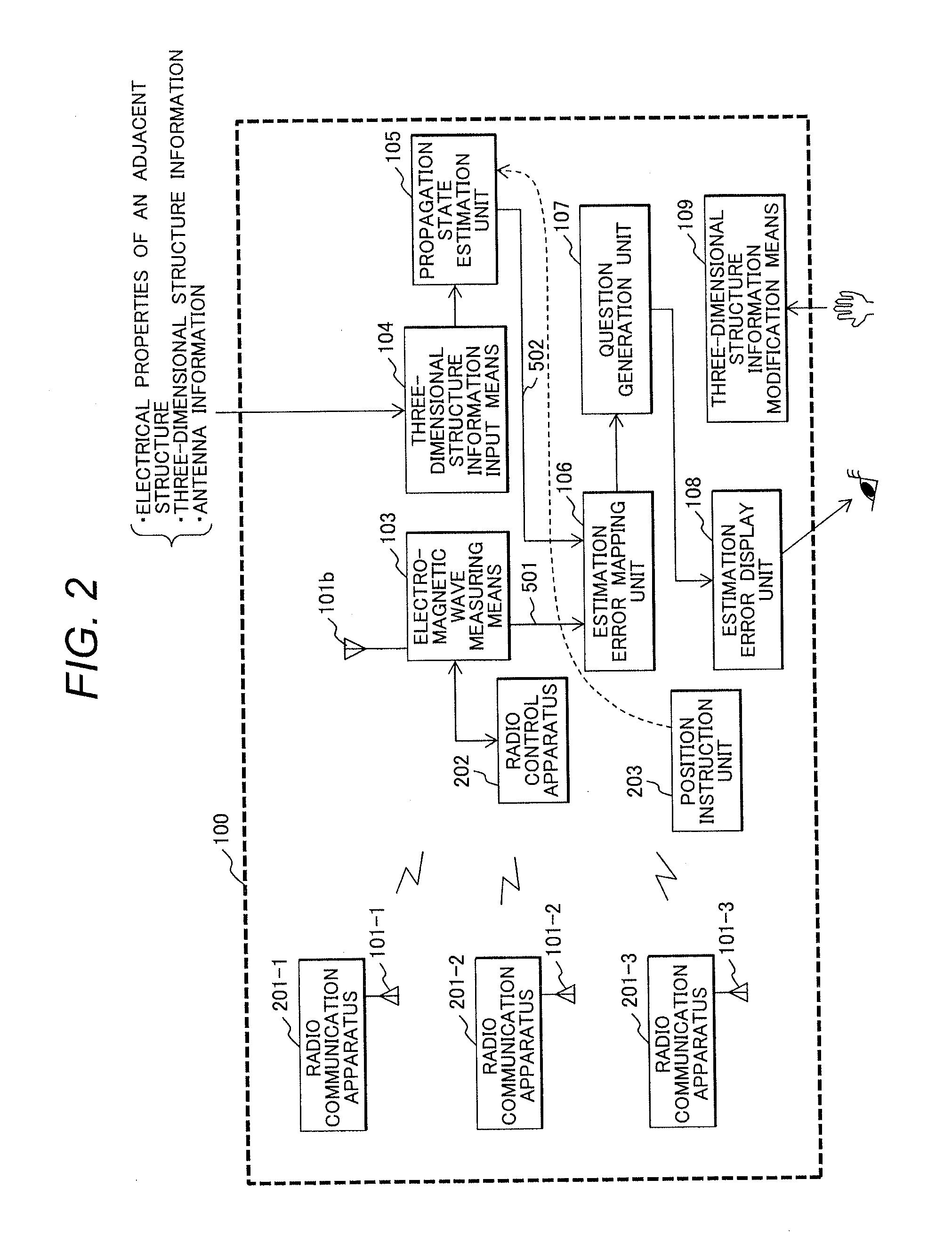
[0125]FIG. 2 shows a second embodiment of the present invention. A principal objective of the first embodiment is to measure the radio wave propagation environment and to modify information about the structures or the like included in the site. That of a second embodiment, on the other hand, is to provide a wireless network construction system which, when the antenna is disposed in a position having an unfavorable communication environment, can teach a more appropriate position.
[0126]The radio wave propagation environment measuring apparatus 100 of FIG. 2 differs from that of FIG. 1 that the electromagnetic wave transmission means 102 is composed of multiple radio communication apparatuses 201 and that a radio control apparatus 202 and a position instruction unit 203 are included.
[0127]As shown in FIG. 13, the radio communication apparatuses 201-1 to 201-3 are disposed in positions at the site at which a wireless network system is planned to be constructed and communicate with one a...
third embodiment
[0132]A radio wave propagation environment measuring apparatus according to a third embodiment of the present invention includes a material property database.
[0133]In the questions 1203 and 1204 about the change of the material in FIG. 12, a predetermined number of ones of the material properties registered in the material property database with respect to the direction of change of each property and the amount of error are listed in the descending order of correlation. The user selects from among the listed material properties.
[0134]This is possible by, with respect to the amounts of error attributable to the electrical material properties and the directions of excessively small and excessively large, obtaining the difference between the yet-to-be-modified electrical material properties and the amount of reflection attenuation, the amount of transmission attenuation, and the amount of diffraction attenuation based on each characteristic value in the material property database and t...
PUM
 Abstract
Description
Claims
Application Information
 - R&D
- Intellectual Property
- Life Sciences
- Materials
- Tech Scout
- Unparalleled Data Quality
- Higher Quality Content
- 60% Fewer Hallucinations
Browse by: Latest US Patents, China's latest patents, Technical Efficacy Thesaurus, Application Domain, Technology Topic, Popular Technical Reports.
© 2025 PatSnap. All rights reserved.Legal|Privacy policy|Modern Slavery Act Transparency Statement|Sitemap|About US| Contact US: help@patsnap.com


