
Current detection circuit

Inactive Publication Date: 2014-05-01
SANKEN ELECTRIC CO LTD
View PDF4 Cites 3 Cited by
  • Summary
  • Abstract
  • Description
  • Claims
  • Application Information

AI Technical Summary

Benefits of technology

The present invention allows for detecting the primary side current of a current transformer without using a matching resistor. This reduces resistance loss when the winding ratio of the current transformer is small. This results in a current detection circuit with low loss and low cost using a small and inexpensive current transformer.

Problems solved by technology

However, with the prior art, there has been a problem that it is difficult to meet all the requirements for the degree of resistance loss W of the resistor R2 as a matching resistor, and the size and cost of the current transformer CT.
Increasing the turns ratio N would provide a larger-sized current transformer CT, which leads to an increase in cost.
Contrarily, lowering the turns ratio N in order to make the current transformer CT smaller in size would increase the resistance loss W. Thus, between the resistance loss W and the turns ratio N of the current transformer CT, there is a contradictory relationship, and therefore it is difficult to satisfy the requirements for both at the same time.

Method used


Image

  • Current detection circuit
  • Current detection circuit
  • Current detection circuit

Examples


Embodiment Construction

[0023]Next, an embodiment of the present invention will be specifically explained with reference to the drawings.

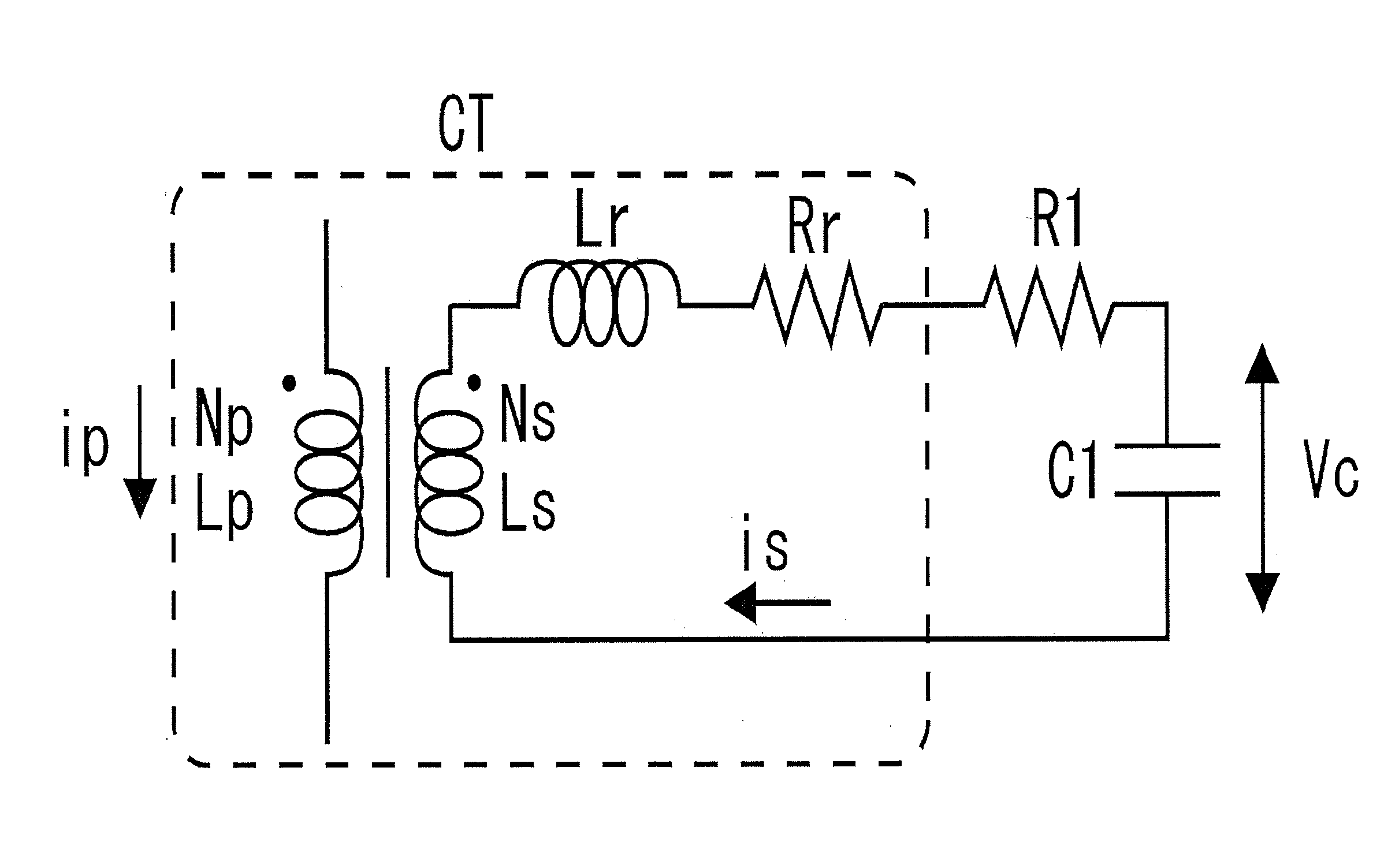
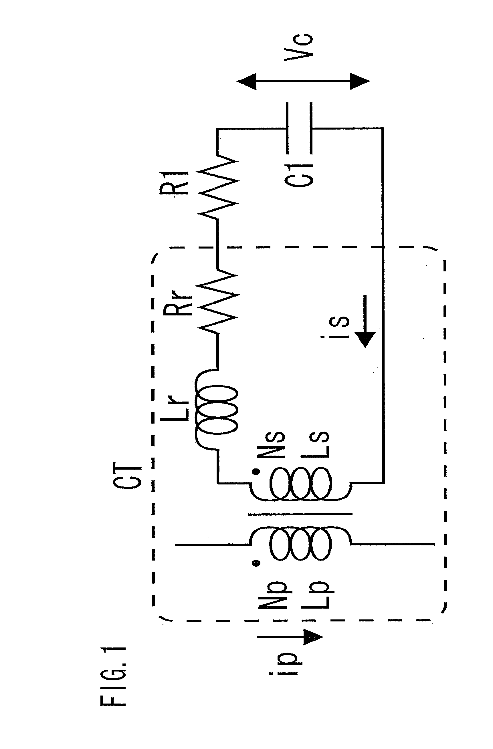
[0024]As shown in FIG. 1, the current detection circuit of the present embodiment includes a current transformer CT, a primary winding Np thereof being installed in a line where to detect the current, and a series circuit of a resistor R1 and a capacitor C1 connected across a secondary winding Ns of the current transformer CT.

[0025]The series circuit of the resistor R1 and the capacitor C1 is a circuit for making phase adjustment of the secondary side voltage of the current transformer CT. Assuming that the resistance value of the resistor R1 is R, and the capacitance of the capacitor C1 is C, the R·C is set to satisfy a relation of the following expression “Math 1”.

R·C=Ls+LrRr[Math1]

[0026]In FIG. 1 and “Math 1”, reference symbol Ls denotes the secondary side inductance of the current transformer CT; Lr the secondary side leakage inductance of the current transformer CT; ...


PUM


Abstract

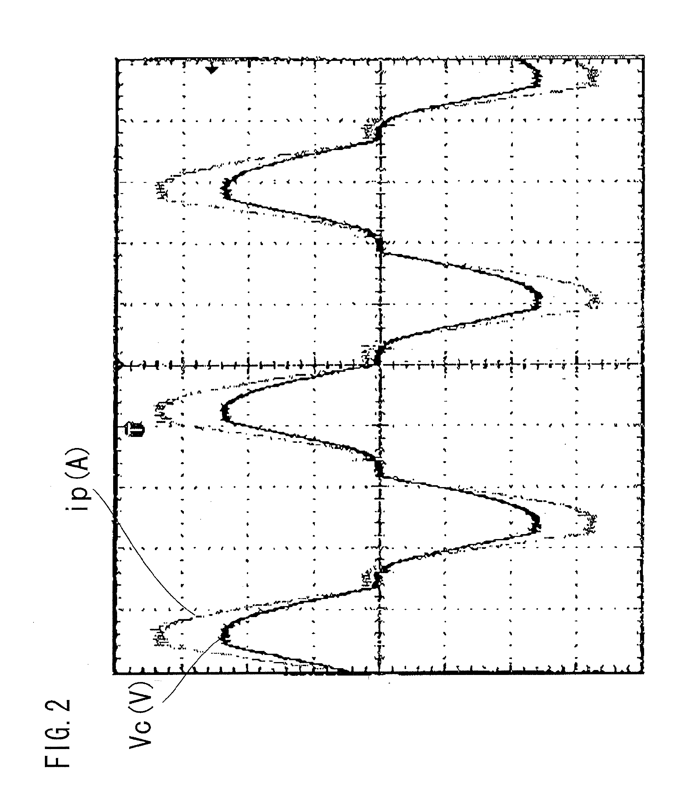
Provided is a current detection circuit which can reduce the resistance loss for a current transformer, meeting the requirements for size and cost thereof. The current detection circuit includes a current transformer and a capacitor connected across a secondary winding of the current transformer, the capacitor making a phase adjustment such that the primary side current flowing through the primary winding of the current transformer and the voltage across the capacitor are in phase with each other. With this configuration, the primary side current can be detected as the voltage across the capacitor with no need for using a matching resistor, with which, if the winding ratio of the current transformer is small, the resistance loss will be large, whereby a current detection circuit of low loss using a current transformer which is small in size and low in cost can be configured.

Description

BACKGROUND OF THE INVENTION [0001]1. Field of the Invention[0002]The present invention relates to a current detection circuit using a current transformer.[0003]2. Description of the Related Art[0004]As shown in FIG. 5, the conventional current detection circuit using a current transformer includes a current transformer CT, a primary winding Np thereof being installed in a line where to detect the current, and a resistor R2 installed across a secondary winding Ns of the current transformer CT. The resistor R2 installed across the secondary winding Ns is called a matching resistor, and across the terminals of the resistor R2, there is outputted a voltage Vs corresponding to a primary side current ip flowing through the line in which the primary winding Np is installed (for example, refer to Patent Document 1).[0005]Patent Document 1: Japanese Unexamined Patent Application Publication No. 2007-299838[0006]However, with the prior art, there has been a problem that it is difficult to mee...

Claims


Application Information

Patent Timeline
IPC IPC(8): G01R19/00
CPCG01R19/0092G01R15/183
Inventor CHIBA, AKITERUISHIKURA, KEITA
Owner SANKEN ELECTRIC CO LTD
Learn More