Filament Wound Composite Ball

a composite ball and filament wound technology, applied in the direction of sealing/packing, other domestic objects, borehole/well accessories, etc., can solve the problems of ineffective fracture treatment, high temperature and pressure limitation of existing composite fracturing ball technology, and achieve high temperature rating and high shear strength

Inactive Publication Date: 2014-05-01
WEATHERFORD TECH HLDG LLC
View PDF2 Cites 39 Cited by
  • Summary
  • Abstract
  • Description
  • Claims
  • Application Information

AI Technical Summary

Benefits of technology

[0014]The filament wound ball offers higher shear strength due to the continuous fiber orientations formed in layers within the wound ball. Additionally, the filament wound mat

Problems solved by technology

Yet, to operate properly, the composite balls need to withstand high fracture pressures and need to maintain their shape engaging the seats under such pressures.
If the ball deforms or fails, then the fluid seal it provides with the seat will be compromised and make t

Method used


Image

  • Filament Wound Composite Ball
  • Filament Wound Composite Ball
  • Filament Wound Composite Ball

Examples


Embodiment Construction

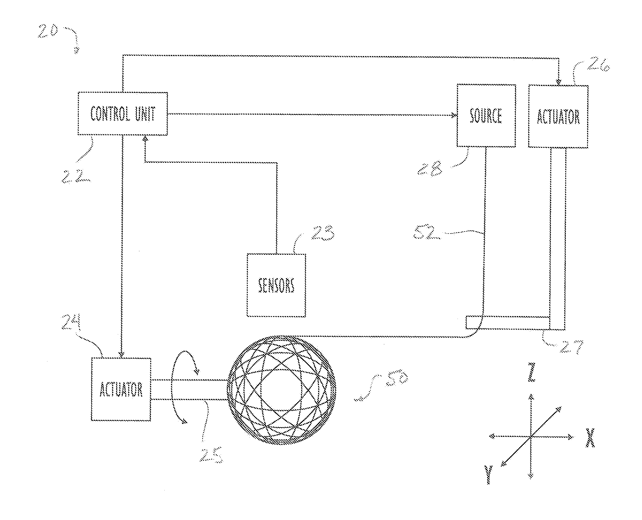
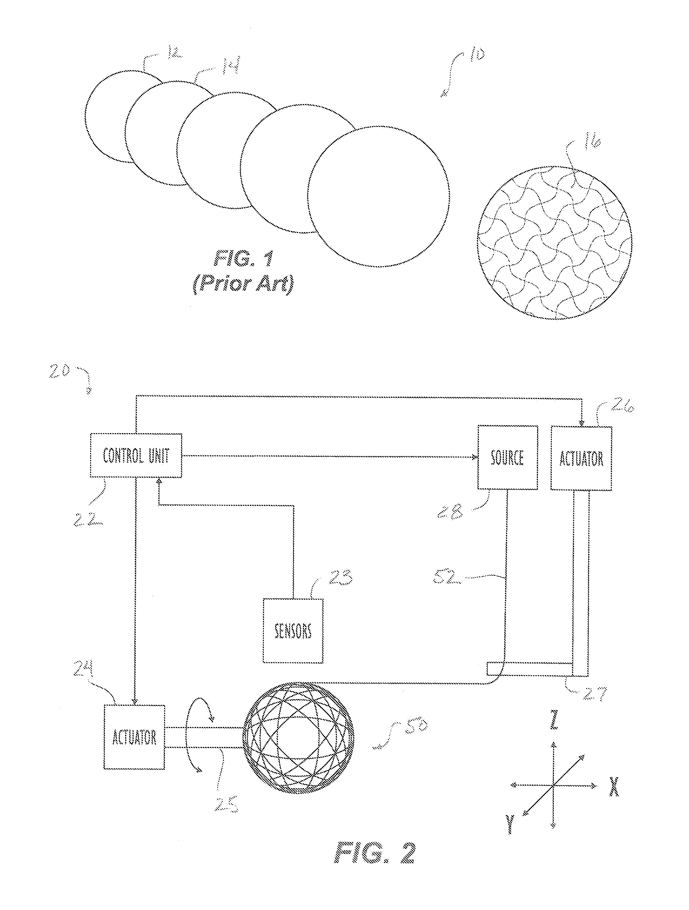
[0025]FIG. 2 schematically illustrates a system 20 for winding a composite ball 50 according to the present disclosure for use in downhole operations. The system 20 includes a multi-axis filament winding machine that is capable of articulating (i.e., rotating and translating) in multiple axes (e.g., 4 to 6 axes). As schematically shown, the system 20 includes a control unit 22 operatively coupled to one or more actuators—only two actuators 24 and 26 are shown for simplicity. The actuators 24 and 26 can be linear and rotational actuators. The control unit 22 controls the actuators 24 and 26 to control the winding of filament 52 from a filament source 28 to form the composite ball 50 during a filament winding procedure.

[0026]As shown here, a first actuator 24 has a spindle 25 on which the composite ball 50 is formed, and the first actuator 24 may be capable of articulating the spindle 25 in a number of suitable ways while forming the composite ball 50. A second actuator 26 has a payou...


PUM


Abstract

A composite ball is formed with wound filament in a winding machine by winding the filament on a core, which can be permanent and form part of the finished ball. Alternatively, the core can be temporary. When winding is completed, the wound body is removed from the winding machine, an exterior of the wound body is finished, and the wound body is cured. When the core is permanent, at least a portion of the core is removed from the winding machine along with the wound body so any excess of the permanent core can be removed. The temporary core, however, is removed from the wound body, and the void is filled with filler material.

Description

CROSS-REFERENCE TO RELATED APPLICATIONS[0001]This application claims the benefit of U.S. Provisional Appl. 61 / 718,978, filed 26 Oct. 2012, which is incorporated herein by reference in its entirety and to which priority is claimed.BACKGROUND OF THE DISCLOSURE[0002]Balls are used in wellbores for a number of purposes. For example, balls may be deployed to operate various downhole tools, such as packers, cross-over tools, valves, etc. In a particular example, different-sized balls 10 as shown in FIG. 1 may be deployed to open sliding sleeves on a tubing string to perform treatment operations at various zones of the wellbore.[0003]The balls 10 can be composed of a number of suitable materials 16 and may be subjected to various types of conditions (pressures, temperatures, fluid compositions, etc.). Aluminum balls are used in some applications, while composite balls are used in others. Some balls may even be composed of dissolvable materials so that the balls degrade in the wellbore envi...

Claims


Application Information

Patent Timeline
IPC IPC(8): E21B33/12
CPCB29D99/0042E21B33/12B29C53/76Y10T428/2922
Inventor ROCHEN, JAMES
Owner WEATHERFORD TECH HLDG LLC
Why Eureka
Try Eureka