Aortic valve and conduit graft implant tool

Active Publication Date: 2014-05-01
EDWARDS LIFESCIENCES CORP
View PDF4 Cites 9 Cited by
  • Summary
  • Abstract
  • Description
  • Claims
  • Application Information

AI Technical Summary

Benefits of technology

[0010]By using the sizing tool described herein, the surgeon can simultaneously size the aortic valve while assessing the transposition of the coronary arteries and anastomosis sites, namely whether one or two additional tubular coronary segments will be required. The conduit graft replica simulates the lower portion or sinus region of the conduit graft as it bulges outward during systole and diastole, more so in the latter phase. First, the valve sizer is inserted into the aortic valve to determine the diameter. Once the correctly-sized valve sizer is properly positioned, the surgeon can assess whether the coronary arteries are long enough to reach the conduit graft repli

Problems solved by technology

Valve disease can be severely debilitating and even fatal if left untreated.
Sometimes the native sinuses bulge outward quite far, and the replacement graft is not shaped the same resulting in a gap between the coronary buttons and the side of the graft.
This proce

Method used


Image

  • Aortic valve and conduit graft implant tool
  • Aortic valve and conduit graft implant tool
  • Aortic valve and conduit graft implant tool

Examples


Embodiment Construction

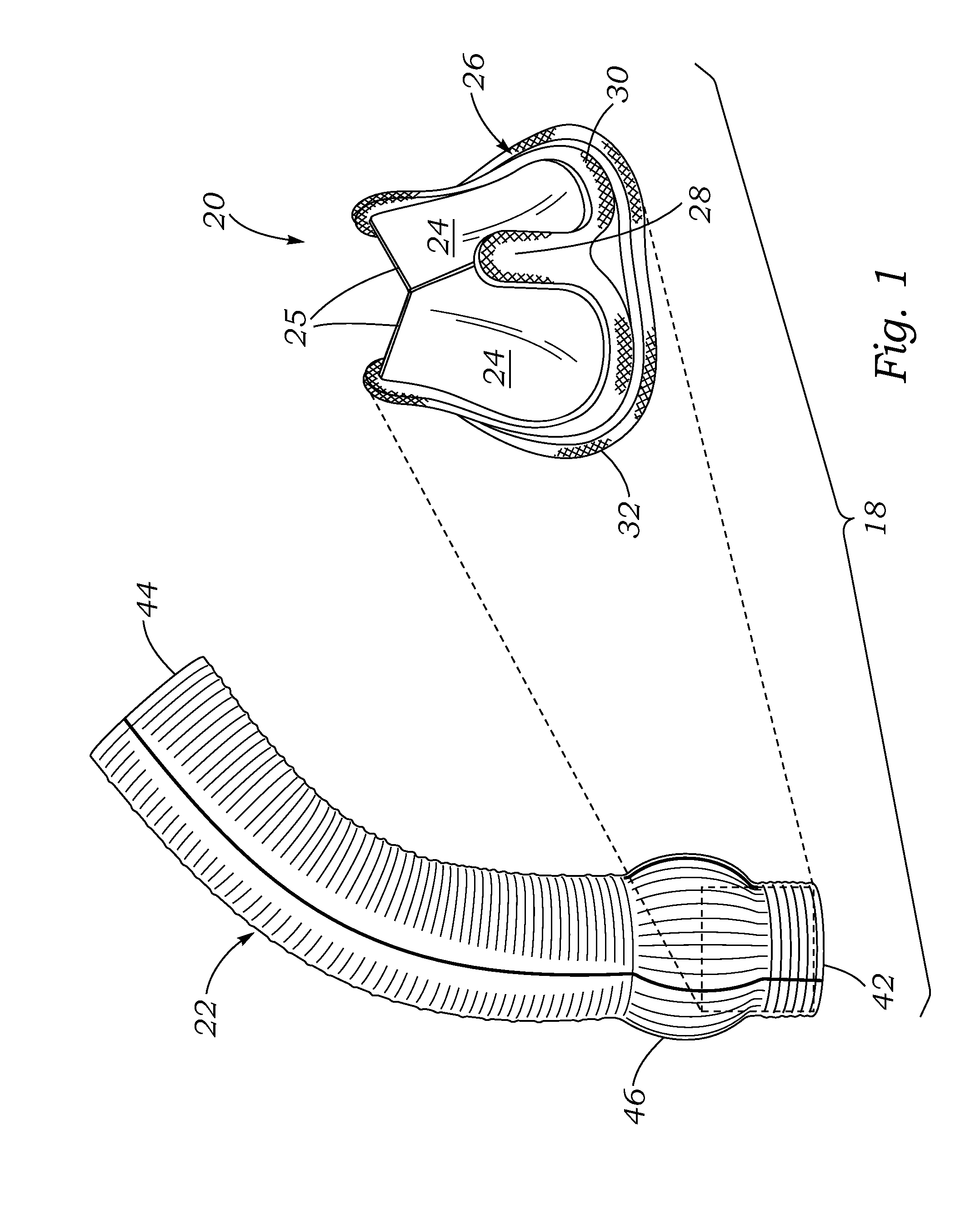
[0029]FIG. 1 is an exploded view of an exemplary composite valved conduit 18 formed by the combination of a bioprosthetic heart valve 20 coupled to a sealed conduit graft 22. As suggested schematically, the prosthetic heart valve 20 is positioned within one end of the conduit graft 22. Such a valved conduit may be used for replacing a native heart valve and an associated blood vessel in a patient. The aortic valve and the ascending aorta are one non-limiting example of such a valve and an associated blood vessel. The pulmonary valve and the pulmonary artery are another such example.

[0030]The heart valve 20 may include a rigid or semi-rigid stent or be a so-called “stentless” type. In the illustrated embodiment, the heart valve 20 comprises a plurality of flexible leaflets 24 (typically three) that are mounted to a peripheral stent structure 26 and form fluid occluding surfaces within the valve orifice to form a one-way valve. The leaflets may be made of various materials, though bio...


PUM


Abstract

A sizing tool for use in implanting a composite valved conduit having a prosthetic heart valve on a distal end attached to a conduit graft that extends to a proximal end. The tool includes a proximal handle and a distal shaft, a prosthetic heart valve sizer having an axis affixed to a distal end of the shaft, and a conduit graft replica having an axis mounted on the shaft proximal to the heart valve sizer. A method of securing a composite valved conduit includes introducing to an excised ascending aorta the sizing tool, measuring the aortic annulus with the prosthetic heart valve sizer, and determining whether the coronary arteries have sufficient length or whether an additional tubular coronary extension segment is required to add to one or both of the ends of the coronary arteries by extending the coronary arteries toward the conduit graft replica.

Description

RELATED APPLICATIONS[0001]The present application claims priority under 35 U.S.C. §119 to U.S. Provisional Application Ser. No. 61 / 719,275, filed Oct. 26, 2012.FIELD OF THE INVENTION[0002]The present invention relates generally to tools and methods for implanting a prosthetic cardiac implant, in particular a combined aortic valve and conduit graft.BACKGROUND OF THE INVENTION[0003]Heart valve disease is a widespread condition in which one or more of the valves of the heart fails to function properly. Valve disease can be severely debilitating and even fatal if left untreated. Physicians use a variety of prostheses to correct problems associated with diseased heart valves. A typical procedure involves removal of the native valve and surgical replacement with a prosthetic heart valve.[0004]Aortic and pulmonary heart valves are positioned at the connection of arteries to the left and right heart ventricles, respectively. Replacement or repair of these valves may involve disconnecting an...

Claims


Application Information

Patent Timeline
IPC IPC(8): A61F2/24
CPCA61F2/2427A61F2/06A61F2/2496
Inventor DE PAULIS, RUGGEROMURAD, MICHAEL C.
Owner EDWARDS LIFESCIENCES CORP
Why Eureka
Try Eureka