Control system for ac electric motor

a control system and electric motor technology, applied in the direction of motor/generator/converter stopper, dynamo-electric gear control, dynamo-electric converter control, etc., can solve the problem of reducing the quietness of the vehicle due to the occurrence of electromagnetic noise, dc voltage fluctuations may lead to torque fluctuations in an ac electric motor, etc. problem, to achieve the effect of reducing the electromagnetic noise of the boost converter and reducing the output fluctuation o

Active Publication Date: 2014-05-08
DENSO CORP
View PDF2 Cites 34 Cited by
  • Summary
  • Abstract
  • Description
  • Claims
  • Application Information

AI Technical Summary

Benefits of technology

[0009]It is an object of the present invention is to restrain output fluctuations in an AC electric motor without increasing electromagnetic noise of a boost converter.
[0010]According to an aspect of the present invention, a control system for an AC electric motor includes a boost converter, an inverter, a pulse width modulation control unit, a rectangular-wave voltage control unit, and a phase restriction control unit. The boost converter is configured to execute bidirectional DC electric power conversion between a power storage device and an electric power line such that a DC voltage on the electric power line is controlled in accordance with a voltage command value. The inverter is configured to convert the DC voltage on the electric power line into an AC voltage to be applied to the AC electric motor. The pulse width modulation control unit is configured to control the AC voltage output from the inverter to the AC electric motor by pulse width modulation control based on a comparison between a sinusoidal voltage command signal for operating the AC electric motor in accordance with a torque command value and a carrier signal. The rectangular-wave voltage control unit is configured to control the AC voltage output from the inverter to the AC electric motor such that a rectangular wave voltage is applied from the inverter to the AC electric motor when a modulation degree of the AC voltage by the pulse width modulation control on the DC voltage exceeds a predetermined reference value. The rectangular-wave voltage control unit controls the inverter in accordance with the torque command value such that an absolute value of a voltage phase of the rectangular wave voltage is increased when the absolute value of torque of the AC electric motor is increased. The phase restriction control unit operates the AC electric motor such that rectangular wave voltage control is avoided from being performed in a state where the absolute value of the voltage phase falls within a region exceeding a limit phase set in accordance with the DC voltage and a rotational speed of the AC electric motor.
[0015]Preferably, the control system is configured such that a plurality of AC electric motors mounted on an electric-powered vehicle are electrically connected in common to the electric power line via a plurality of inverters, respectively. The plurality of AC electric motors include a first electric motor as an electric motor for driving the electric-powered vehicle. The control system further includes a torque command value setting unit and a torque command value correction unit. The torque command value setting unit sets a torque command value for each of the plurality of AC electric motors in accordance with an operating state of the electric-powered vehicle. The phase restriction control unit decreases the torque command value for the first electric motor when the absolute value of the voltage phase obtained by the rectangular wave voltage control at the DC voltage at present exceeds the limit phase. When the torque command value for the first electric motor is decreased by the phase restriction control unit, the torque command value correction unit corrects the torque command value for electric motors other than the first electric motor so as to compensate for a reduction in vehicle driving force caused by the decrease.
[0018]In this control system for an AC motor, output fluctuations in an AC electric motor can be restrained without increasing electromagnetic noise of a boost converter.

Problems solved by technology

As regarded as a problem in PTD 1 as well, in such a control system that variably controls a DC link voltage of an inverter by a boost converter, fluctuations in DC voltage may lead to torque fluctuations in an AC electric motor.
However, as described in PTD 1, if fluctuations in DC voltage are restrained by reducing the carrier frequency of the boost converter, a new problem that electromagnetic noise occurs may arise.
In particular, in a control system for an AC electric motor mounted on an electric-powered vehicle, such as a hybrid vehicle, reduction in quietness in the vehicle due to the occurrence of electromagnetic noise is of concern.

Method used


Image

  • Control system for ac electric motor
  • Control system for ac electric motor
  • Control system for ac electric motor

Examples


first embodiment

Variation of First Embodiment

[0155]In the control system for an AC electric motor according to the first embodiment, the opportunity of applying the rectangular wave voltage control is reduced by the phase limit correction control so as to prevent torque fluctuations in the rectangular wave voltage control. This is not preferable in terms of reduction in loss in the control system. On the other hand, if fluctuations in system voltage VH do not occur, torque fluctuations will not occur even if the voltage phase in the rectangular wave voltage control is large. Therefore, execution of the phase limit correction control is preferably applied only in the state where there is concern about fluctuations in system voltage VH.

[0156]For example, as described in PTD 1 as well, when a passing current of reactor L1 of boost converter 12, that is, input / output current Ib of DC power source B is around zero, fluctuations in system voltage VH are likely to occur under the influence of dead time in...

second embodiment

[0162]In the first embodiment, execution of the rectangular wave voltage control in a range where the voltage phase is large is avoided by raising system voltage VH so as to avoid the transition from the PWM control to the rectangular wave voltage control. The second embodiment will describe control for restricting the voltage phase when the rectangular wave voltage control is applied.

[0163]FIG. 16 is a functional block diagram illustrating a control configuration for setting a system voltage command value in a control system for an AC electric motor according to a second embodiment.

[0164]Referring to FIG. 16, voltage command value setting unit 500# according to the second embodiment sets voltage command value VH# for system voltage VH when the rectangular wave voltage control is selected.

[0165]Voltage command value setting unit 500# has phase limit map 535, a base command value generation unit 560, a phase limit correction unit 570, and a voltage command value operation unit 580.

[0...

third embodiment

[0174]As described above, AC electric motor M1 to be subjected to control in the present embodiment is representatively a traction motor of an electric-powered vehicle. A plurality of AC electric motors may be mounted on an electric-powered vehicle. With such a configuration, in the case where inverters for controlling a plurality of AC electric motors, respectively, has a common DC link voltage, it is important to prevent torque fluctuations in a specific AC electric motor having a great influence on vehicle driving force.

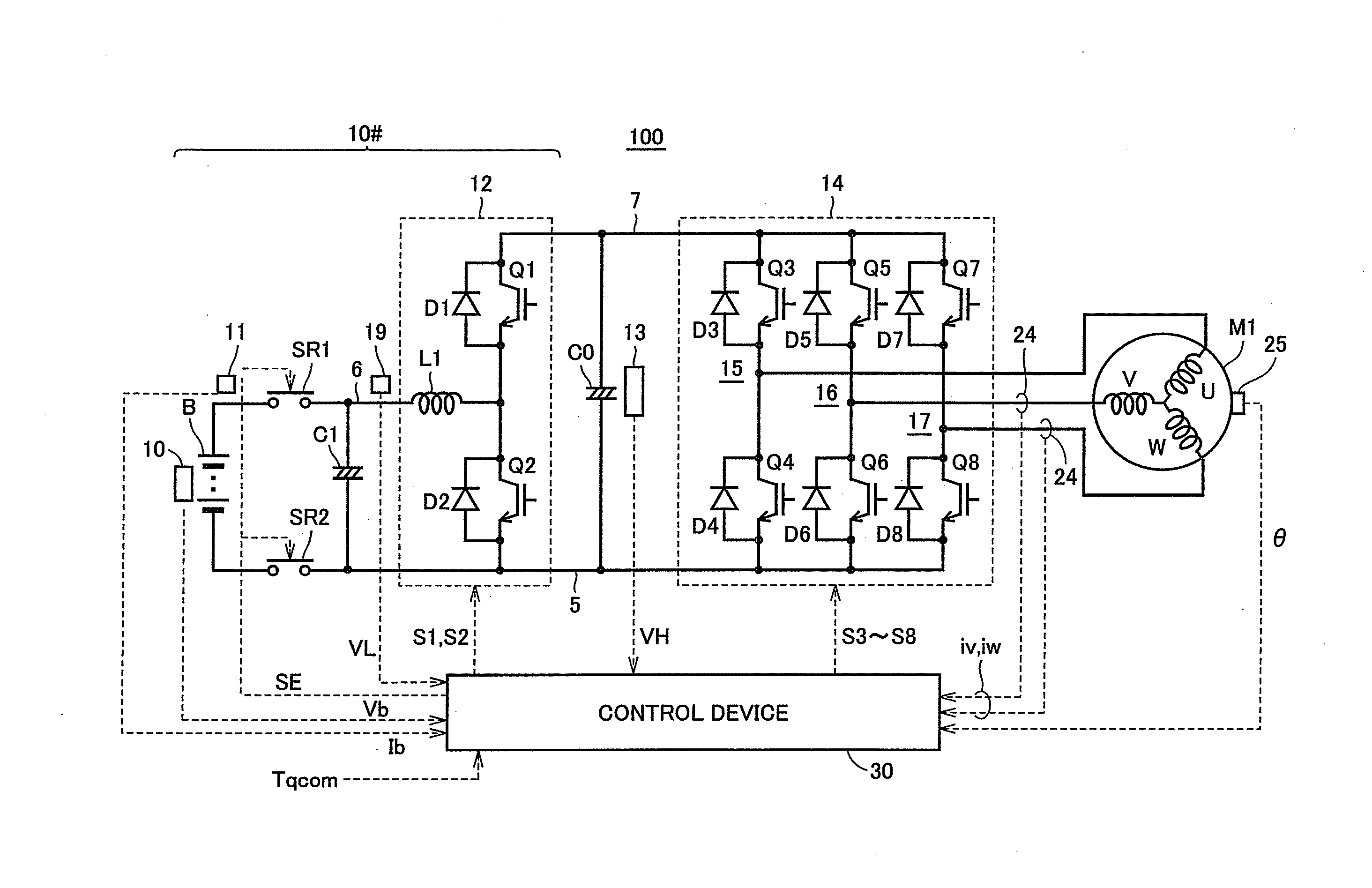
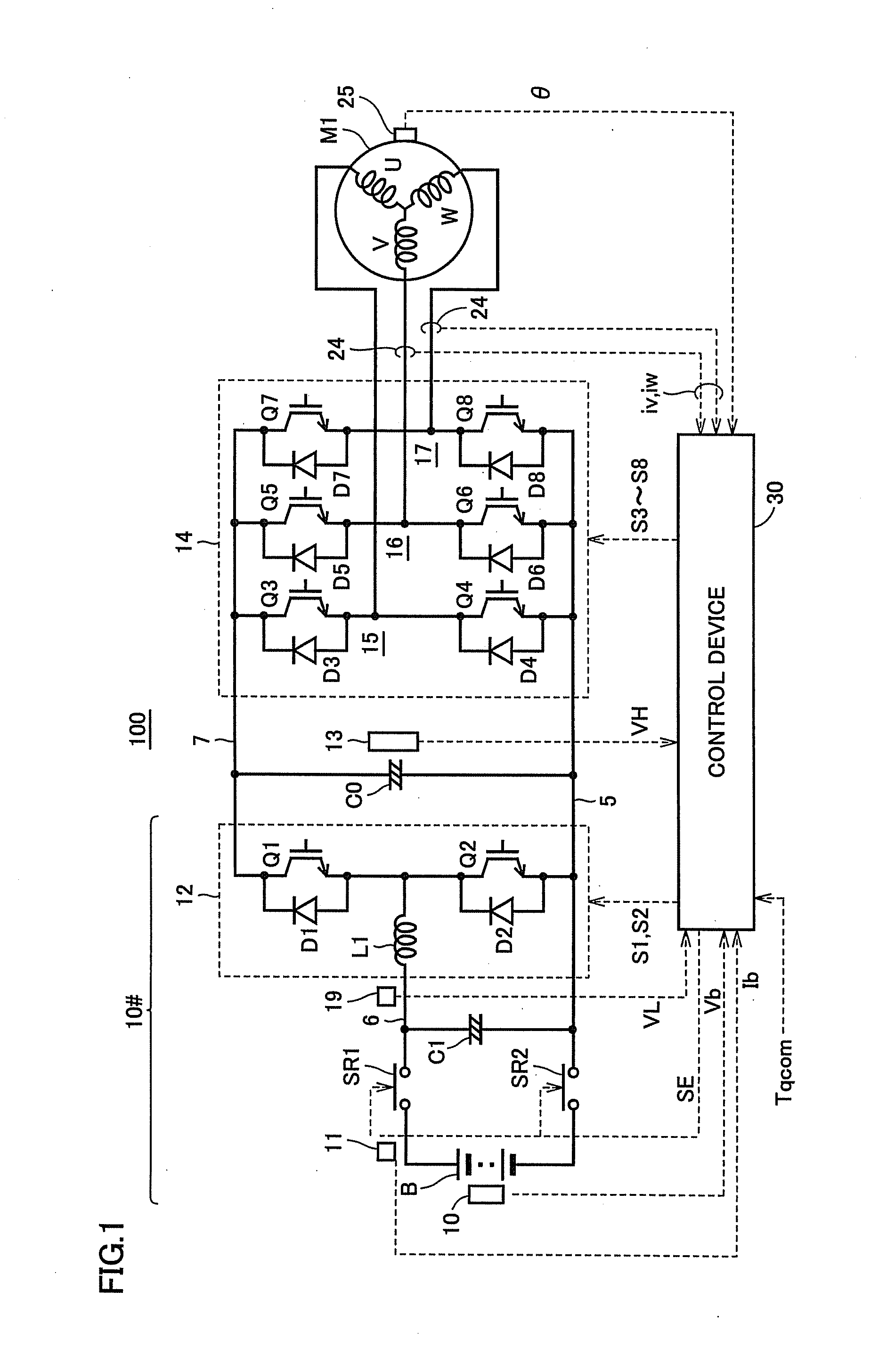
[0175]FIG. 17 is a schematic block diagram illustrating an exemplary configuration of an electric-powered vehicle on which a control system for an AC electric motor according to a third embodiment of the present invention is mounted.

[0176]Referring to FIG. 17, a hybrid vehicle 800 shown as a representative example of an electric-powered vehicle includes an engine 805, a first MG (Motor Generator) 810 (hereinafter also referred to as “MG1”), a second MG 820 (herein...


PUM


Abstract

Fluctuations in output of an AC electric motor are restrained without increasing electromagnetic noise of a boost converter. When subjecting the AC electric motor to rectangular wave voltage control, output torque T is controlled by varying a voltage phase φv. In a region where a voltage phase is large (φv=θ2), fluctuations in torque T relative to changes in a DC voltage VH corresponding to the amplitude of a rectangular wave voltage are larger than in a region where the voltage phase is small (φv=θ1). The AC electric motor is controlled such that the rectangular wave voltage control in a region where voltage phase φv is larger than a limit-phase line PLN indicated by a set of limit phases set for each DC voltage VH is avoided.

Description

[0001]This nonprovisional application is based on Japanese Patent Application No. 2012-245297 filed with the Japan Patent Office on Nov. 7, 2012, the entire contents of which are hereby incorporated by reference.BACKGROUND OF THE INVENTION[0002]1. Field of the Invention[0003]The present invention relates to a control system for an AC electric motor, and more particularly to a control system in which a DC link voltage of an inverter that drives an AC electric motor is variably controlled by a converter.[0004]2. Description of the Background Art[0005]In order to control an AC electric motor through use of a DC power source, a control system by means of an inverter is used. In particular, a structure that variably controls a DC link voltage of an inverter by a boost converter is known, as described in Japanese Patent Laying-Open No. 2004-112904 (PTD 1). As for such a control system, PTD 1 describes control for reducing the influence of dead time of a switching element (transistor) on / o...

Claims


Application Information

Patent Timeline
Patent Type & Authority Applications(United States)
IPC IPC(8): H02P6/10H02P6/06H02P6/08H02P6/28H02P21/00H02P21/05H02P21/22H02P23/04H02P27/06H02P27/08
CPCH02P6/10H02P27/085H02P21/0089H02M3/1582
Inventor NAKAMURA, MAKOTOYAMAZAKI, MIKIO
Owner DENSO CORP
Why Eureka
Try Eureka