Electronic eye marking/registration

a technology of eye marking and eye registration, applied in medical science, diagnostics, skiascopy, etc., can solve the problems of unaccounted and uncorrected astigmatism error in post-operative eye, inaccuracy and/or accuracy of hand-based astigmatic axis marking using surgical marker pen, etc., to improve the astigmatism correction/neutralization outcome

Inactive Publication Date: 2014-05-08
CLARITY MEDICAL SYST
View PDF2 Cites 31 Cited by
  • Summary
  • Abstract
  • Description
  • Claims
  • Application Information

AI Technical Summary

Benefits of technology

[0012]In another example embodiment, pre-operative eye property measurement data are compared with real time intra-operative eye property measurement data and the measurement data are used to further improve the astigmatism correction / neutralization outcome. In this respect, a pre-operative measurement of keratometry / keratoscopy or corneal topography or OCT (optical coherence tomography) or wavefront or auto-refraction or a combination of two or more of these measurements can be compared with an intra-operative measurement of keratometry / keratoscopy or corneal topography or OCT (optical coherence tomography) or wavefront or auto-refraction or a combination of two or more of these measurements. The changes in the optical property of the eye such as changes to spherical or cylindrical refractive errors resulting from surgical factors can be determined to enable the calculation of a true target astigmatism correction / neutralization axis.

Problems solved by technology

Traditional hand based astigmatic axis marking using a surgical marker pen generally is not accurate and / or precise as the thickness of the pen mark along with the fact that the mark “bleeds” / wicks out over a wider area causes additional meridian error covering an angular range of several to many degrees.
In addition, the astigmatic axis measurement which is generally based on keratometry / keratoscopy or corneal topography does not take into account the contributions to astigmatism from the posterior corneal surface and potentially the contribution from the crystalline lens.
All these can lead to unaccounted and uncorrected astigmatism error in a post-operative eye.

Method used


Image

  • Electronic eye marking/registration
  • Electronic eye marking/registration
  • Electronic eye marking/registration

Examples


Embodiment Construction

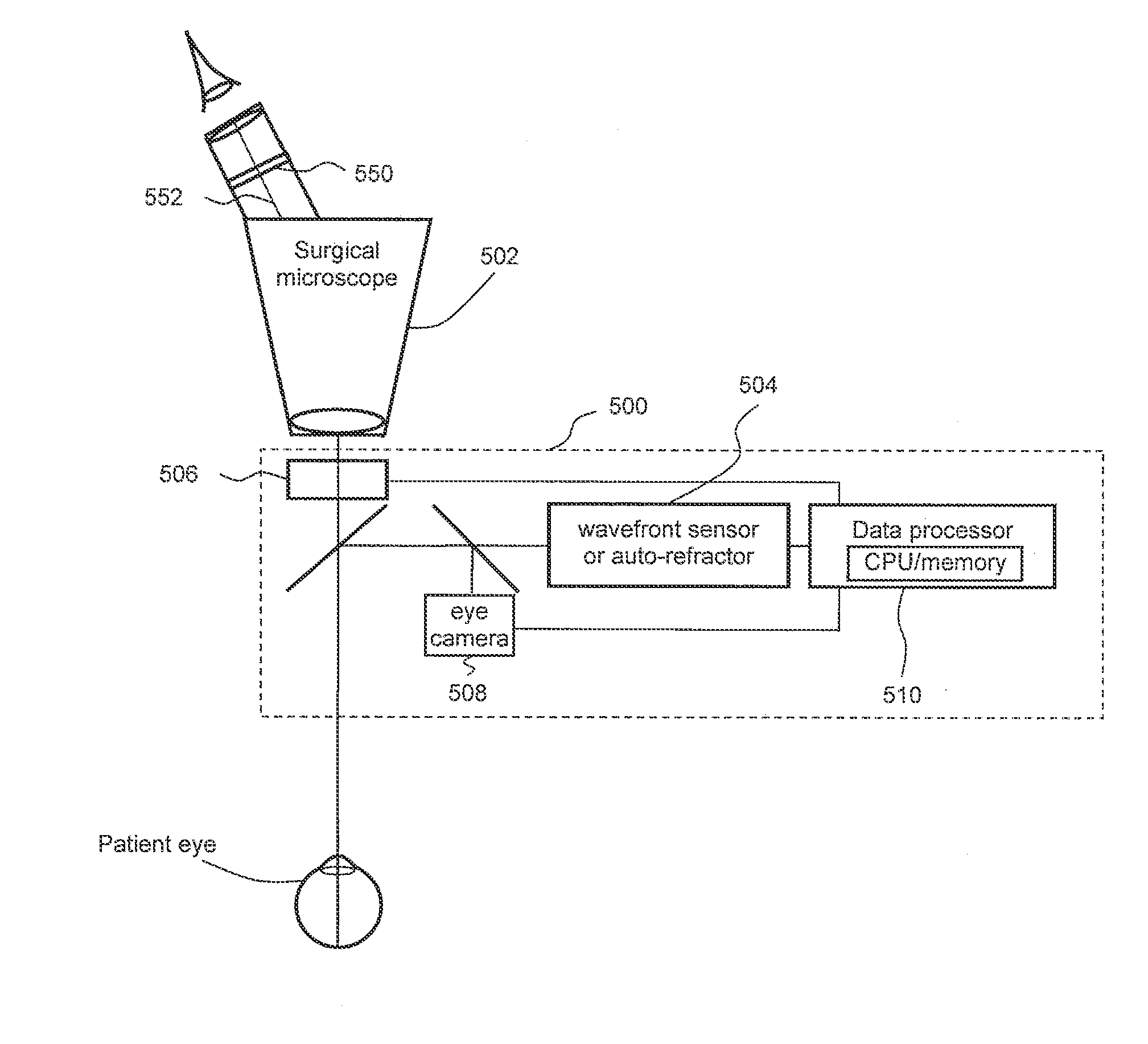
[0029]In one or more embodiments of the present invention, an image of the patient eye and an electronically marked reference axis for astigmatism correction / neutralization is presented to a surgeon during eye surgery without requiring any additional reticle projection hardware to be combined with a surgical microscope. In other embodiments of the present invention, the astigmatism correction / neutralization axis is more accurately and / or precisely determined by taking into consideration the changes in the astigmatic property of a patient eye before, during and after a refractive surgery. Furthermore, the electronically generated custom indicator(s) of the astigmatism correction / neutralization axis is (are) overlaid onto and registered with a live image of a patient eye on a display.

[0030]In the following discussion various types of surgically induced factors will be discussed and various methods of compensating these factors will be described. To simplify the following discussion th...


PUM


Abstract

One embodiment is a method for finding, calculating and electronically marking a reference axis for astigmatism correction/neutralization of a patient eye during a refractive surgery.
The reference axis for astigmatism correction/neutralization can be determined intra-operatively based on one or more eye property measurements together with simultaneous recording a live eye image. The determined reference axis of astigmatism correction/neutralization can be updated and registered with one or more land mark(s) of the recorded eye image(s); and overlaid onto a live image of the eye. Another embodiment is a method of calculating and displaying in real time compensated refractive errors of the eye under operation with refractive components due to temporary surgically induced factors removed and refractive components due to surgeon-induced factors added.

Description

RELATED APPLICATION[0001]This application claims priority from provisional application No. 61 / 723,254 entitled Electronic Eye Marking / Registration filed Nov. 6, 2012 which is incorporated by reference for all purposes.TECHNICAL FIELD OF THE INVENTION[0002]One or more embodiments of the present invention relate generally to electronic eye marking / registration for vision correction procedure(s). In particular, the embodiments are related to determining a reference axis for astigmatism, astigmatism correction and electronically marking / registering / recording custom indicator(s) that tracks and overlays a live image of an eye.BACKGROUND OF THE INVENTION[0003]In a traditional cataract refractive surgery, the refractive astigmatic axis of the cornea anterior surface, the cornea, or the eye of a patient is measured or determined prior to surgery. In the following the term astigmatic axis defines the location of the axis or meridian of an astigmatic eye. A mark, (using ethylene blue marker, ...

Claims


Application Information

Patent Timeline
Patent Type & Authority Applications(United States)
IPC IPC(8): A61B3/00
CPCA61B3/0058A61B3/0041A61B3/0025A61B3/036A61B3/103A61B3/1035A61B3/1176
Inventor SHEA, WILLIAMZHOU, YAN
Owner CLARITY MEDICAL SYST
Why Eureka
Try Eureka