Real time dynamic physics simulation device of flexible DC transmission system

a dynamic simulation and transmission system technology, applied in the field of real-time dynamic simulation devices of flexible hvdc transmission systems, can solve the problem that rtds can only realize off-line tests, and achieve the effects of accurate understanding of operation characteristics, compact structure, and convenient radiating and debugging

Active Publication Date: 2014-05-08
STATE GRID CORP OF CHINA +1
View PDF4 Cites 67 Cited by
  • Summary
  • Abstract
  • Description
  • Claims
  • Application Information

AI Technical Summary

Benefits of technology

[0024]The present invention can accurately simulate 20-100MVA capacity, different voltage level flexible DC transmission system based on modular multilevel converter (MMC-HVDC), and can capable of responding to accurately understand the operation characteristics of MMC-HVDC and the dynamic responds to the instruction of the control system.
[0025]The converter of the invention adopts modular design so that it has compact structure, and convenient radiating and debugging.
[0...

Problems solved by technology

However, the converter valve level number is less than 15 of the present physical simulation prototype which is...

Method used


Image

  • Real time dynamic physics simulation device of flexible DC transmission system
  • Real time dynamic physics simulation device of flexible DC transmission system
  • Real time dynamic physics simulation device of flexible DC transmission system

Examples


embodiment 1

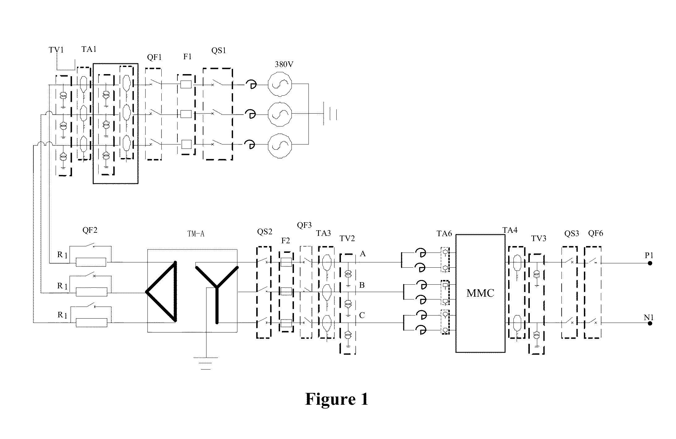
[0029]FIG. 1 is the structure schematic diagram and the sensor layout of main circuit of the embodiment. It includes simulated converter transformer, simulated AC field, simulated DC field, simulated converter reactor, simulated converter, and measurement and control cabinet chassis. The simulated AC field includes the vacuum switch I, the contactor I, resistors and the vacuum switch II which are connected orderly. The simulated DC field includes successively connected the vacuum switch contactor III and II. The simulated AC field is connected with measurement and control cabinet chassis. The converter transformer is set between resistors and the vacuum switch II. The simulated converter reactors connected and the simulated converter are set between the vacuum switch II and the vacuum switch III, and the contactor III and resistors are connected in parallel and set between the vacuum switch II and the vacuum switch III. In the embodiment, the resistors and adjustable reactor are use...

embodiment 2

[0056]The embodiment is same to embodiment 1 except below differences:

[0057](1) The negative impedance compensator is stringed into MMC converter bridge arm to balance out part voltage drop of arm semiconductors. The compensation characteristics of the compensator are obtained directly by the arm current direction and the voltage balance control strategy.

[0058](2) another voltage\current acquisition board is added between the contactor I and converter transformer primary side voltage\current acquisition board. The former acquisition board can control the voltage\current signal, while new added acquisition board can recode signal.


PUM


Abstract

The present invention relates to a real time dynamic physics simulation device of flexible DC transmission system. The device includes simulated converter transformer, simulated AC field, simulated DC field, simulated converter reactor, simulated converter, and measurement and control cabinet chassis; the simulated AC field includes the vacuum switch I, the contactor I, resistors and the vacuum switch II connected orderly; the simulated DC field includes successively connected the vacuum switch contactor III and II; the simulated AC field is connected with said measurement and control cabinet chassis; Said converter transformer is set between said resistors and said vacuum switch II; Said simulated converter reactors and said simulated converter connected are set between the vacuum switch II and the vacuum switch III. The present invention can accurately simulate different voltage level flexible DC transmission system based on modular multilevel converter (MMC-HVDC), able to accurately understand the operation characteristics of MMC-HVDC and the dynamic responds to the instruction of the control system.

Description

RELATED APPLICATIONS[0001]This application is a United States National Stage Application filed under 35 U.S.C 371 of PCT Patent Application Serial No. PCT / CN2011 / 083126, filed Nov. 29, 2011, the disclosure of all of which are hereby incorporated by reference in their entirety.FIELD OF THE INVENTION[0002]The invention relates to DC transmission field, in particular, relates to a real time dynamic physics simulation device of flexible HVDC transmission system.BACKGROUND OF THE INVENTION[0003]The flexible direct current (DC) transmission is at a new transmission method, which adopts direct current for transmission and uses the turn-off voltage source converters and advanced modulation technology to carry out DC transmission. It has some advantages, like supplying power for isolated grid, without commutation failure, no need for reactive power compensation, being able to control flexibly active and reactive power output etc, and it is also a beneficial supplement for the alternating cur...

Claims


Application Information

Patent Timeline
IPC IPC(8): G06F17/50
CPCG06F17/5009G01R31/085G01R31/088G01R31/2848G01R31/086G06F30/20
Inventor HE, ZHIYUANLIU, DONGZHAO, YANYANG, YUEFENGWANG, RENQIU
Owner STATE GRID CORP OF CHINA
Why Eureka
Try Eureka