
Fuel injection valve, internal combustion engine and fuel injection method

a fuel injection valve and internal combustion engine technology, applied in the direction of fuel injection apparatus, combustion engine, charge feed system, etc., can solve the problems of insufficient torque or increase in the emission amount of nosub>x/sub>, inability to solve the above problem, etc., to reduce the amount of fuel injection, reduce the effect of fuel adhesion or the like, and maintain constant total injection amoun

Active Publication Date: 2014-05-15
BOSCH CORP
View PDF10 Cites 6 Cited by
  • Summary
  • Abstract
  • Description
  • Claims
  • Application Information

AI Technical Summary

Benefits of technology

The invention is aimed at reducing the amount of fuel spray that enters certain areas of an engine, such as the cylinder liner and piston crown surface, in order to reduce oil dilution and fuel adhesion. By directing the fuel spray towards areas with high air fluidity, the invention maintains constant injection amount and combustion efficiency. This results in better engine performance and reduced emissions.

Problems solved by technology

Such a fuel spray may cause oil dilution that increases sliding resistance in the engine, fuel adhesion onto the cylinder liner and fuel adhesion onto the piston crown surface relating to soot emission.
Note that reducing the flow rate of the injection holes in order to reduce the penetration of the fuel sprays reaching the cylinder liner or the piston crown surface may cause a shortage of overall injection amount per one combustion, resulting in an insufficient torque or increase in emission amount of NOx.
Furthermore, JP-A-2004-232583 is not intended to reduce the adverse effect of a fuel spray having a strong penetration, so it cannot solve the above problem.

Method used


Image

  • Fuel injection valve, internal combustion engine and fuel injection method
  • Fuel injection valve, internal combustion engine and fuel injection method
  • Fuel injection valve, internal combustion engine and fuel injection method

Examples


Embodiment Construction

[0024]An embodiment relating to a fuel injection valve of the present invention, an internal combustion engine including the fuel injection valve and a fuel injection method using the fuel injection valve is described below with reference to the drawings.

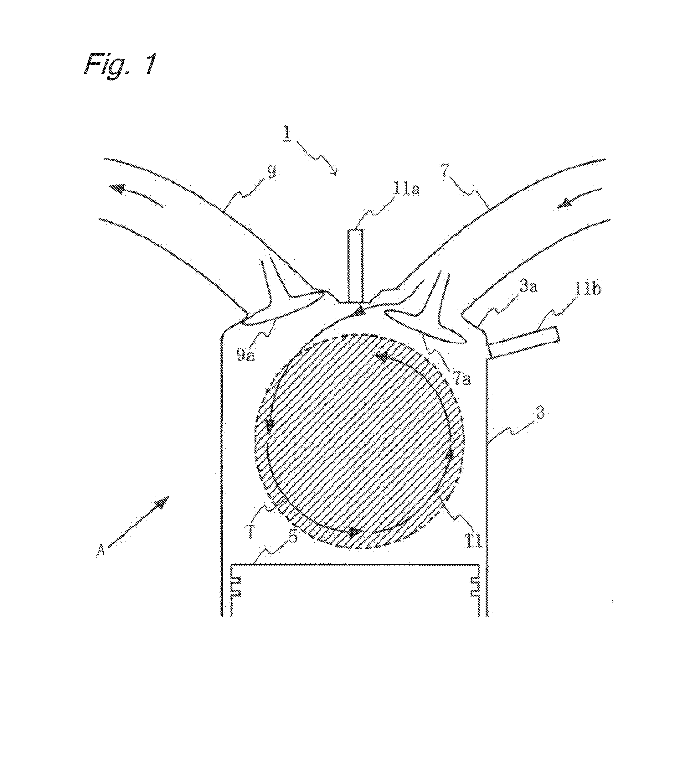
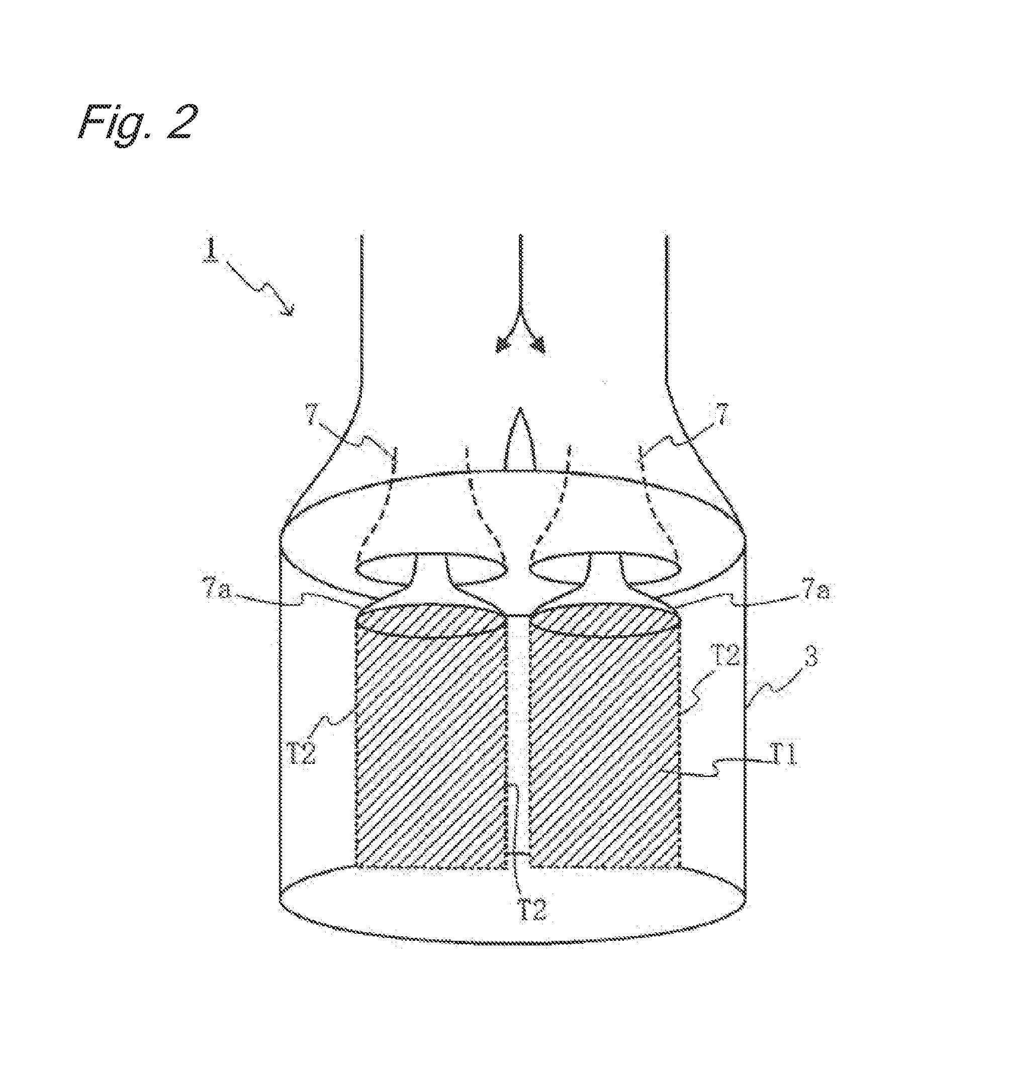
[0025]In the embodiment of the invention, in one fuel injection valve, diameters of a plurality of injection holes directed toward a certain area are varied to vary the injection amount for each injection hole to enable the penetrations to be controlled. However, since the total injection amount of one fuel injection valve needs to be maintained constant, a first group of injection holes of which penetrations (penetration forces) are increased and a second group of injection holes of which penetrations (penetration forces) are reduced are provided.

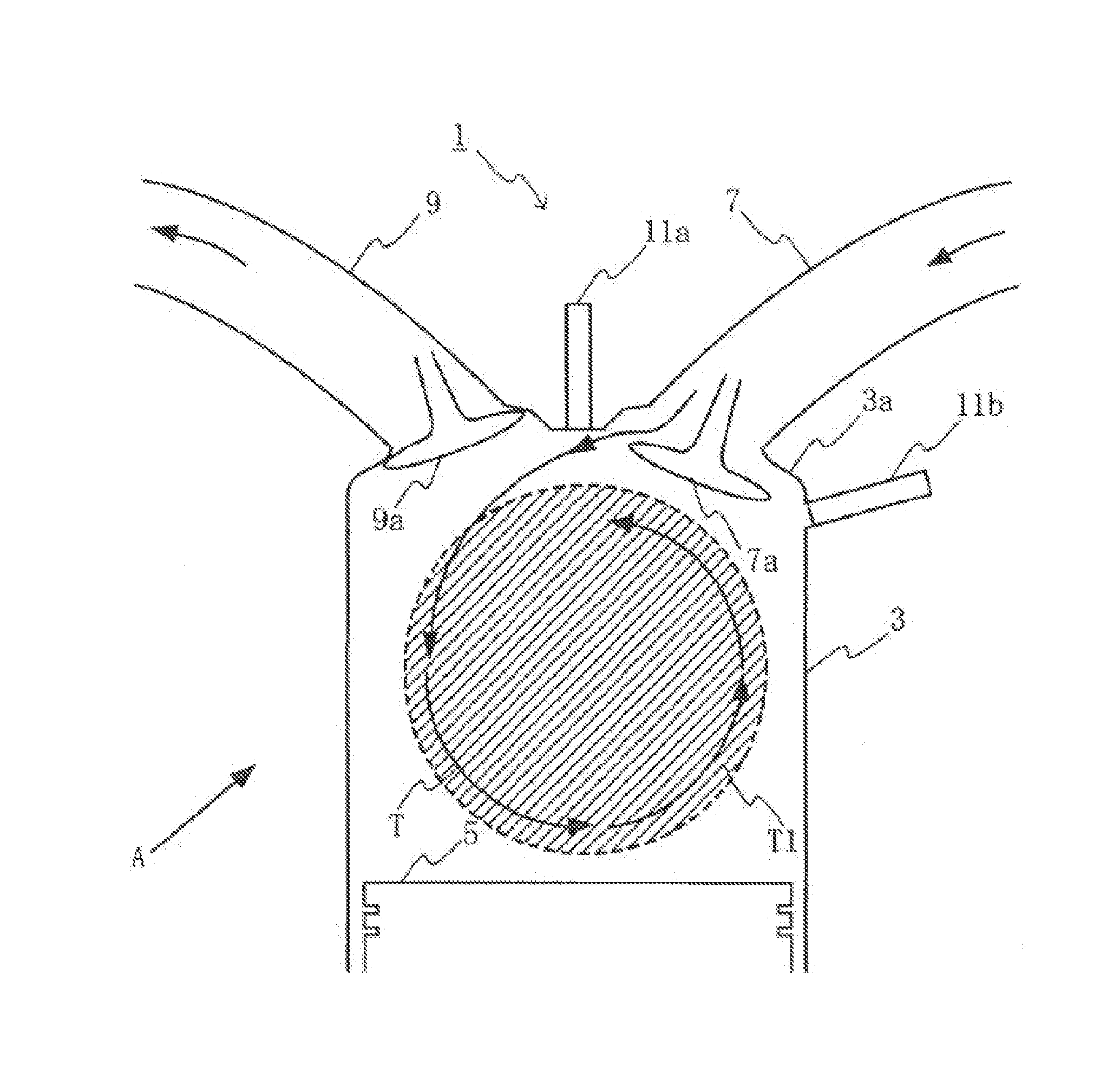
[0026]FIG. 1 shows a conceptual diagram of an internal combustion engine 1 to which the embodiment is to be applied. The internal combustion engine 1 includes: a cylinder 3; a piston 5 pro...


PUM


Abstract

It is an object of the present invention to reduce the penetration of a fuel spray directed toward a certain area in a cylinder, thereby reducing oil dilution that increases sliding resistance in the engine, reducing fuel adhesion or the like onto the cylinder liner, and also reducing the adverse effect of a fuel spray having an increased penetration.A fuel injection valve that has a plurality of injection holes and injects fuel into a cylinder 3 of an internal combustion engine includes: injection holes a2 and a6 having a larger diameter for injecting fuel toward a ring-shaped space T1 including areas A2 and A6 of strong tumble flow T formed in the cylinder; and injection holes al, a4, a3 and a5 having a smaller diameter for injecting fuel toward a space including areas A1, A4, A3 and A5 of weak tumble flow formed in the cylinder 3. A fuel spray from an injection hole having the larger diameter has a penetration force to the tumble flow larger than the penetration force of a fuel spray from an injection hole having the smaller diameter.

Description

BACKGROUND OF THE INVENTION[0001]The present invention relates to a fuel injection valve including injection holes having different diameters, an internal combustion engine including the fuel injection valve and a fuel injection method using the fuel injection valve.[0002]A fuel injection valve used for a typical gasoline engine has a plurality of injection holes. The plurality of injection holes formed in one fuel injection valve have the same diameter. Penetrations of fuel sprays against the air flow in a cylinder depend on the momentum of the fuel sprays from the individual injection holes, and, since the fuel sprays from the same type of injection holes have the same momentum, the penetrations of the individual fuel sprays are the same. Note that a penetration refers to a fuel spray travel distance, however, does not necessarily refers to a final fuel spray travel distance, but often refers to a fuel spray travel distance at a certain point of time. Mentioning the relation betwe...

Claims


Application Information

Patent Timeline
IPC IPC(8): F02M61/18
CPCF02M61/1806F02M61/1813F02M61/1826F02B23/101F02B23/104F02B2023/103F02B2023/106F02B2275/48Y02T10/12
Inventor MAEDA, KAORUGOTO, YUICHIROWIESE, WOLFRAMSCHERRER, DANIEL
Owner BOSCH CORP
Learn More