Heat exchange arrangement

a technology of exchange arrangement and heat exchange, which is applied in the direction of lighting and heating apparatus, process and machine control, instruments, etc., can solve the problems of inability to increase compression ratio or tet, inability to provide further cooling air, and inability to take part in the thermodynamic cycle. , to achieve the effect of accurate control of the flow rate of fluid

Inactive Publication Date: 2014-05-15
ROLLS ROYCE PLC
View PDF7 Cites 32 Cited by
  • Summary
  • Abstract
  • Description
  • Claims
  • Application Information

AI Technical Summary

Benefits of technology

[0022]Preferably, the valve may comprise a butterfly valve. Butterfly valves have been found to be particula

Problems solved by technology

Ultimately, a limit is reached whereby providing further cooling air is ineffective at restoring component operating life, and neither compression ratio nor TET can be increased.
Furthermore, air used in cooling is not generally available to take part in the thermodynamic cycle of the engine.
Consequently, excessive use of compressor air for cooling may result in an increase in specific fuel

Method used


Image

  • Heat exchange arrangement
  • Heat exchange arrangement
  • Heat exchange arrangement

Examples


Embodiment Construction

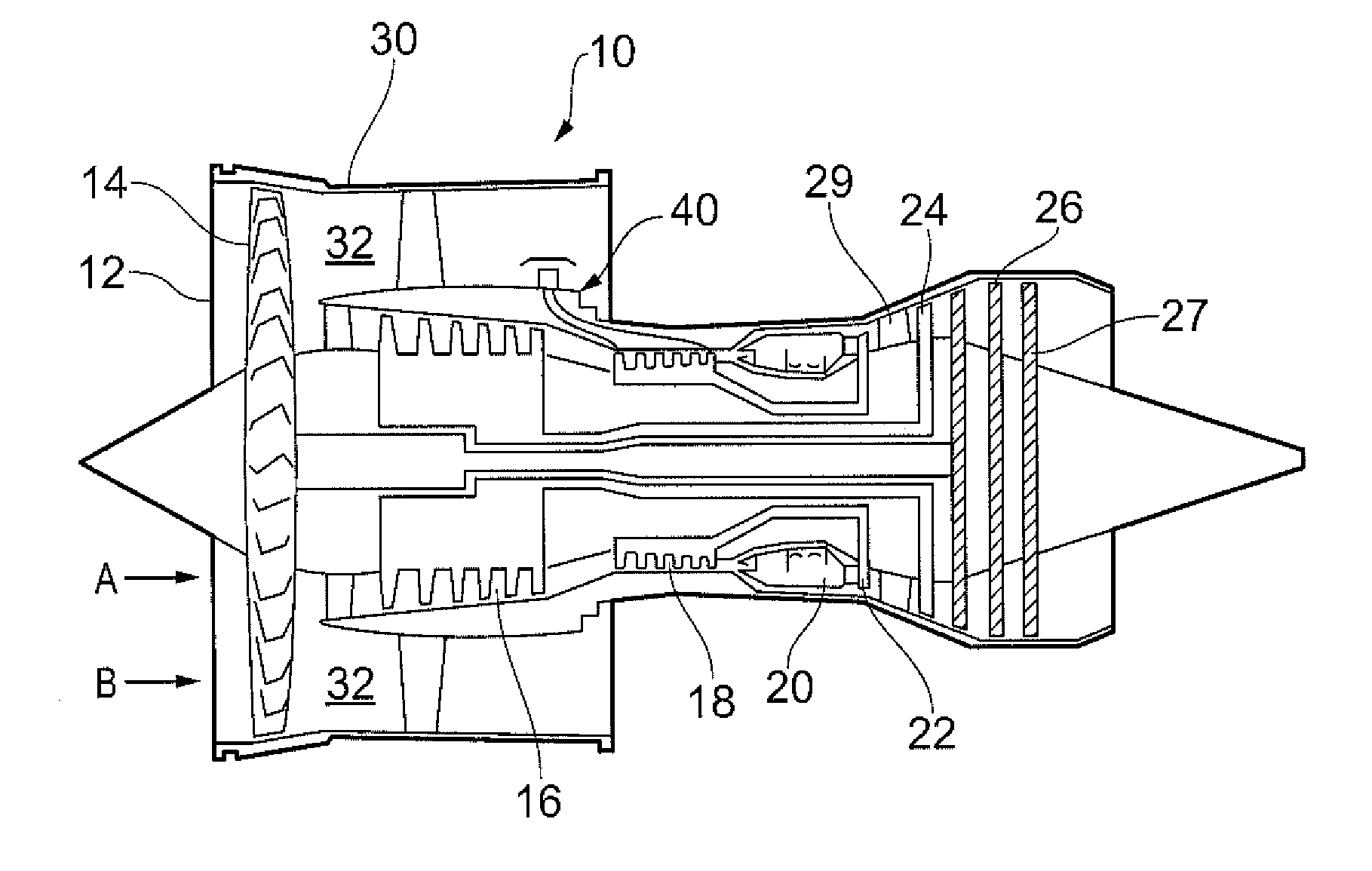
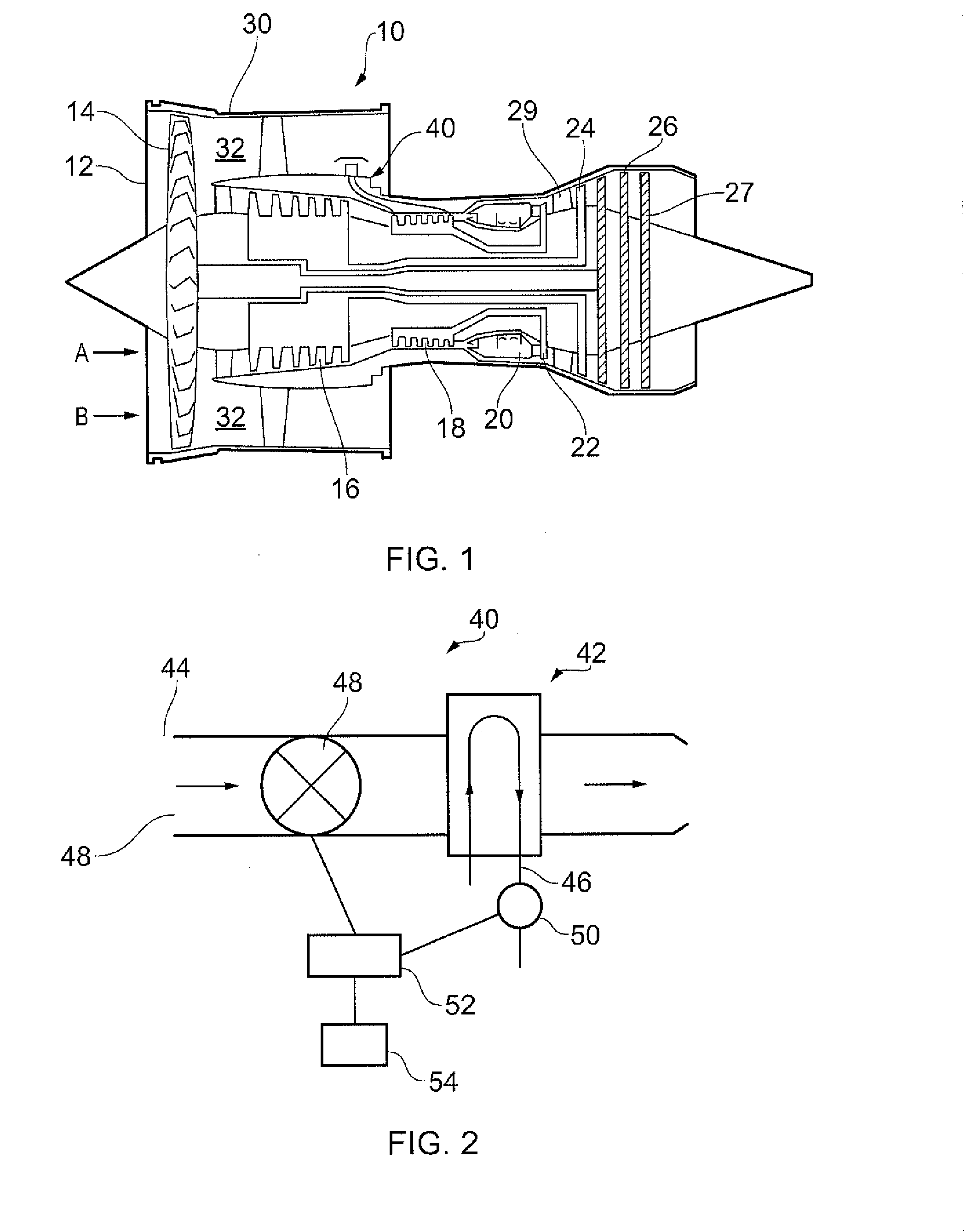
[0028]FIG. 1 shows a gas turbine engine 10 comprising an air intake 12 and a propulsive fan 14 that generates two airflows A and B. The gas turbine engine 10 comprises, in axial flow A, an intermediate pressure compressor 16, a high pressure compressor 18, a combustor 20, a high pressure turbine 22, an intermediate pressure turbine 24, a low pressure turbine 26 and an exhaust nozzle 28. Each turbine 22, 24, 26 comprises rotating turbine rotors 27 and stationary nozzle guide vanes (NGVs) 29. A nacelle 30 surrounds the gas turbine engine 10 and defines, in axial flow B, a bypass duct 32.

[0029]The gas turbine engine 10 includes a heat exchange arrangement 40, as shown diagrammatically in further detail in FIG. 2. The arrangement comprises a first conduit 46 for an engine component cooling fluid. The engine component cooling fluid comprises high pressure compressor air supplied by the high pressure compressor 18, though air could alternatively be supplied from the intermediate pressure ...


PUM


Abstract

A heat exchange arrangement (40) for a gas turbine engine (10). The arrangement (40) comprises a first conduit (46) for an engine component cooling fluid and a second conduit (44) for a second fluid. The arrangement further comprises a heat exchange portion (42) in which fluids flowing through the first and second conduits (46, 44) are in a heat exchange relationship. A valve 48 is provided, which is configured to moderate the mass flow rate of one of the fluids through the heat exchange portion (42). The arrangement comprises a temperature sensor (50) configured to sense a temperature of one of the fluids after said fluid has passed through the heat exchange portion (42) and a controller (52). The controller (52) is configured to control the valve (48) in response to a rate of change of the temperature with respect to time of the fluid sensed by the temperature sensor (50).

Description

FIELD OF THE INVENTION [0001]The present invention relates to a heat exchange arrangement and a method of controlling a heat exchange arrangement, and particularly to a heat exchange arrangement for a gas turbine engine.BACKGROUND TO THE INVENTION [0002]FIG. 1 shows a gas turbine engine 10 comprising an air intake 12 and a propulsive fan 14 that generates two airflows A and B. The gas turbine engine 10 comprises, in axial flow A, an intermediate pressure compressor 16, a high pressure compressor 18, a combustor 20, a high pressure turbine 22, an intermediate pressure turbine 24, a low pressure turbine 26 and an exhaust nozzle 28. Each turbine 22, 24, 26 comprises rotating turbine rotors 27 and stationary nozzle guide vanes (NGVs) 29. A nacelle 30 surrounds the gas turbine engine 10 and defines, in axial flow B, a bypass duct 32.[0003]The air exiting the combustor 20 is generally at a very high temperature, which generally approaches or exceeds the melting point of the materials used...

Claims


Application Information

Patent Timeline
IPC IPC(8): F02C9/00F28F27/00
CPCF28F27/00F02C9/00F02K3/115F02C7/185F05D2270/309F05D2270/303F05D2270/3062F05D2270/702F05D2270/704Y02T50/60
Inventor CHIR, ADAM PHILIP
Owner ROLLS ROYCE PLC
Why Eureka
Try Eureka