High Voltage Energy Harvesting and Conversion Renewable Energy Utility Size Electric Power Systems and Visual Monitoring and Control Systems

US20140132075A1Active Publication Date: 2014-05-15ALENCON ACQUISITION

Image

  • High Voltage Energy Harvesting and Conversion Renewable Energy Utility Size Electric Power Systems and Visual Monitoring and Control Systems
  • High Voltage Energy Harvesting and Conversion Renewable Energy Utility Size Electric Power Systems and Visual Monitoring and Control Systems
  • High Voltage Energy Harvesting and Conversion Renewable Energy Utility Size Electric Power Systems and Visual Monitoring and Control Systems

Examples


Embodiment Construction

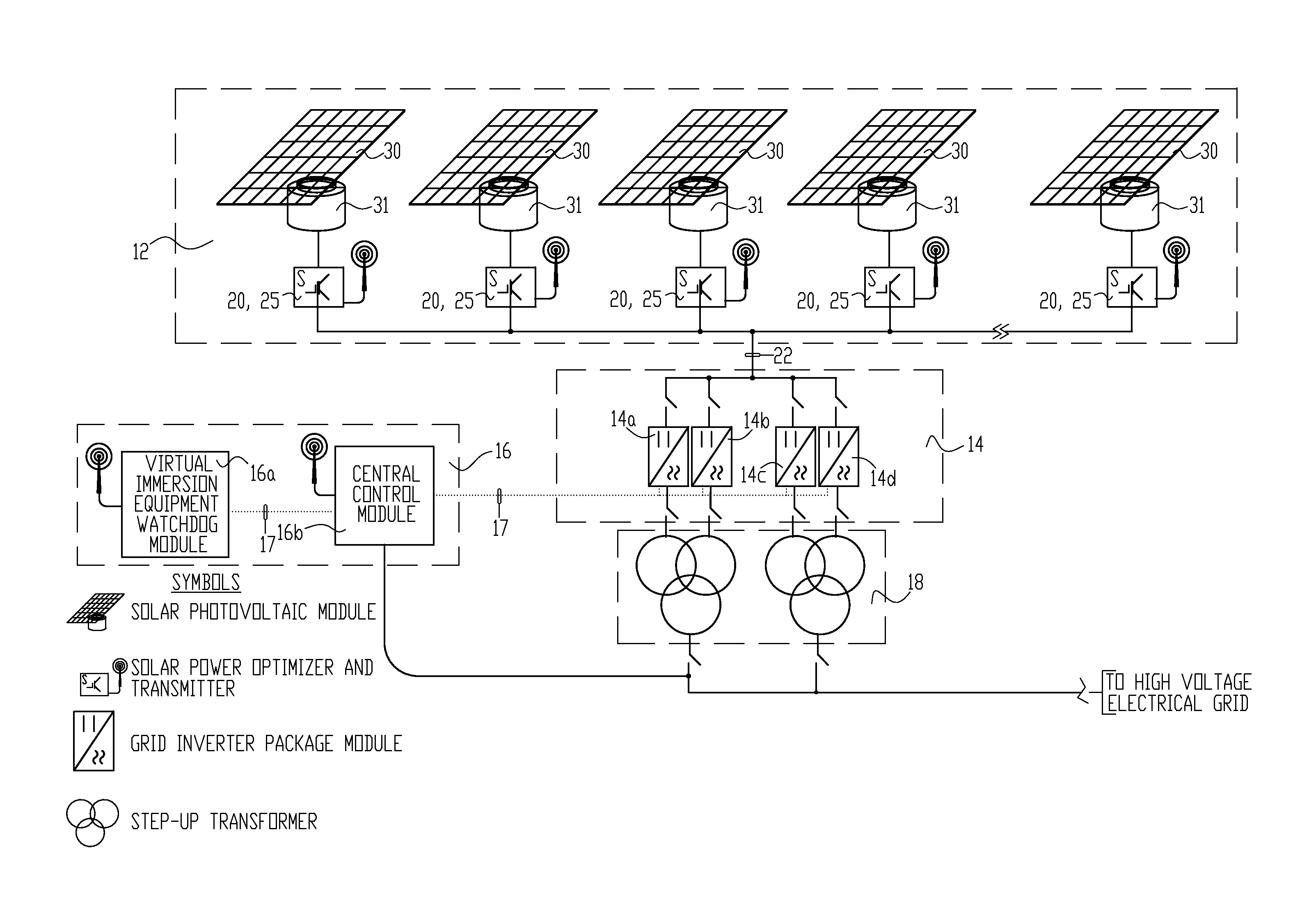
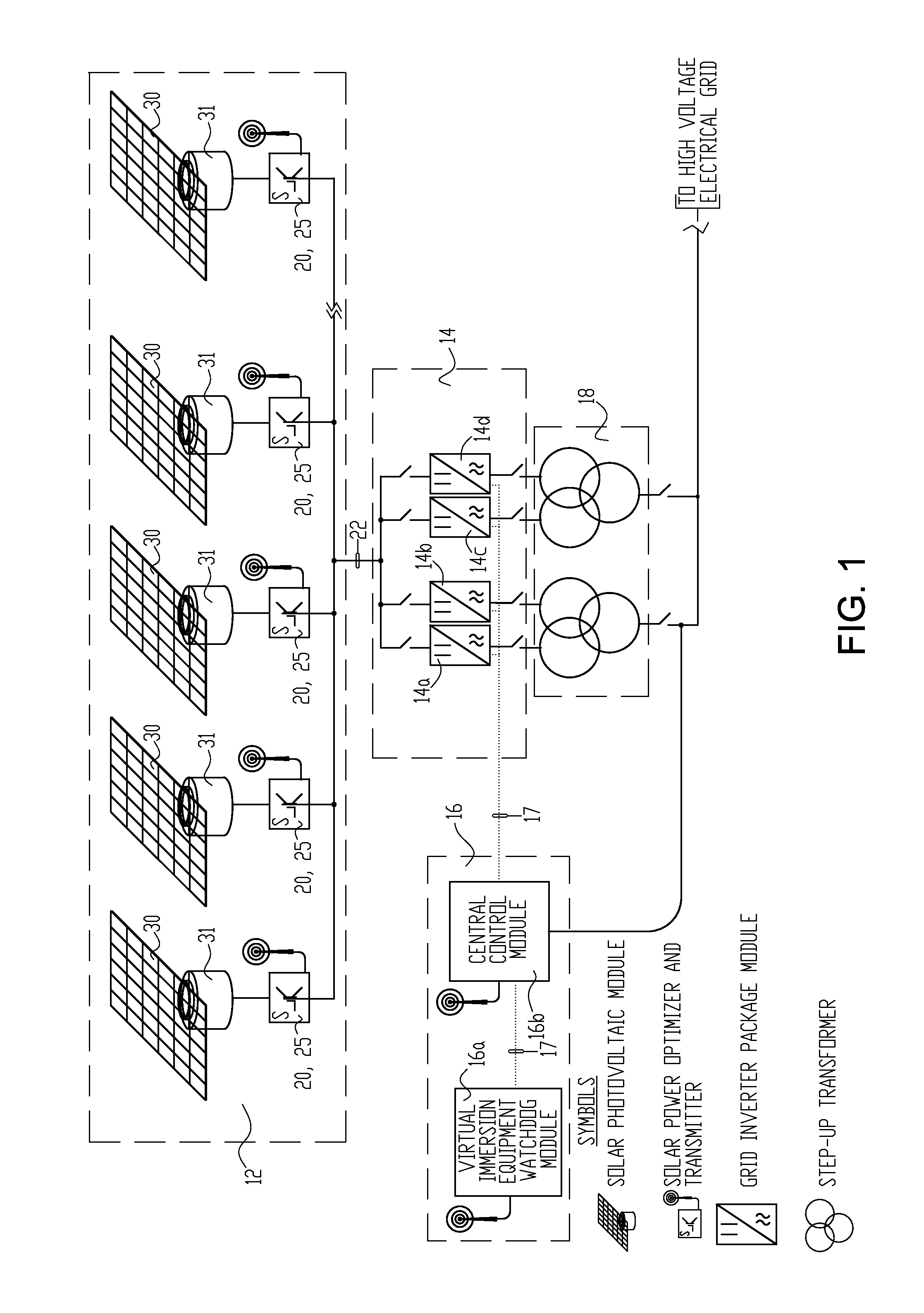
[0024]FIG. 1 is a simplified one-line block diagram of one example of a renewable energy, utility-size electric power system for the collection and conversion of solar energy, and a monitoring and control system of the present invention for the power system. In this example, there is a high voltage, solar photovoltaic energy collection (also referred to as “harvesting”) network 12; a centralized grid synchronized multiphase regulated current source inverter system 14; and an optional virtual immersion monitoring and control system 16. Step-up transformer 18 electrically isolates the outputs of the inverters in the grid inverter package (GrIP) modules 14a-14d from the high voltage electrical grid.

[0025]High voltage, solar photovoltaic energy harvesting networks and centralized grid synchronized multiphase regulated current source inverter systems are further described in U.S. Pat. No. 8,130,518.

[0026]The virtual immersion monitoring and control system comprises the virtual immersion ...


PUM


Abstract

A renewable energy, utility-size electric power system is provided with a high voltage, renewable energy harvesting network connected by a direct current link to a centralized grid synchronized multiphase regulated current source inverter system. The harvesting network includes distributed renewable energy power optimizers and transmitters that control delivery of renewable energy to the grid synchronized multiphase regulated current source inverter system. A visual immersion monitoring and control system can be provided for a three dimensional, visually oriented, virtual reality display, and command and control environment.

Description

FIELD OF THE INVENTION[0001]The present invention relates generally to renewable energy, utility-size electric power systems and, in particular, to high voltage energy harvesting and conversion renewable energy collection and conversion systems, and to visual monitoring and control systems for such systems where a combination of DC-to-DC converters are used.BACKGROUND OF THE INVENTION[0002]The term “renewable energy electric power systems” as used herein refers to utility-size electric power systems that utilize a large number of interconnected photovoltaic modules to form a solar farm or power plant, or a large number of interconnected wind turbine generators that form a wind farm or power plant.[0003]Utility-size (ranging from 5 to 100 megawatt (MWe) output capacity) solar photovoltaic power systems comprise a large number of solar photovoltaic power collectors, such as solar photovoltaic modules, that supply DC electric power to collocated DC to AC inverters that convert the DC p...

Claims


Application Information

Patent Timeline
15 May 2014
Publication
US20140132075A1
IPC
H02J3/38; H02J3/36
CPC
H02J3/36; H02J3/38; H02J1/10; H02J2300/40; H02J2300/24; H02J3/381; Y02E10/56; H02J3/44
Inventors
FISHMAN, OLEG S.; SCHWABE, ULRICH K.W.