Aromatic hydrocarbon production apparatus

a production apparatus and hydrocarbon technology, applied in the direction of hydrocarbon distillation, organic chemistry, separation processes, etc., can solve the problems of large energy consumption, limit in reducing the energy consumption of the whole process, and large energy consumption

Inactive Publication Date: 2014-05-22
TOYO ENG CORP
View PDF1 Cites 22 Cited by
  • Summary
  • Abstract
  • Description
  • Claims
  • Application Information

AI Technical Summary

Benefits of technology

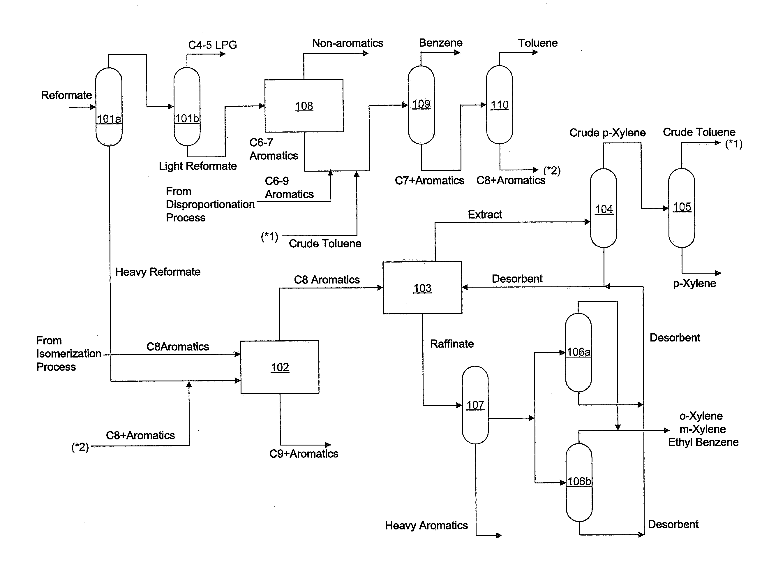
[0098]The aromatic hydrocarbon production apparatus is preferably configured so that the overhead vapor of the fourth distillation apparatus is used as the heat source of one or more reboilers selected from the group consisting of a reboiler provided for the low-pressure distillation column (for example, the low-pressure reformate splitter described later) of the first distillation apparatus and a reboiler provided for the third distillation apparatus (for example, the extract column described later).
[0099]In order to use the overhead vapor of the fourth distillation apparatus as the heat source of a reboiler of a certain distillation column or distillation apparatus (for example, an extract column), this reboiler (for example, the reboiler of the extract column) may be provided with a heat exchange structure for performing heat exchange between the overhead vapor of the fourth distillation apparatus and a column bottom fluid of this distillation column or distillation apparatus (for example, the extract column).
[0100]If the aromatic hydrocarbon production apparatus includes the fifth distillation apparatus (such as the para-xylene purification column described later), the aromatic hydrocarbon production apparatus may be configured so that the overhead vapor of the fourth distillation apparatus is used as a heat source of a reboiler provided for the fifth distillation apparatus.
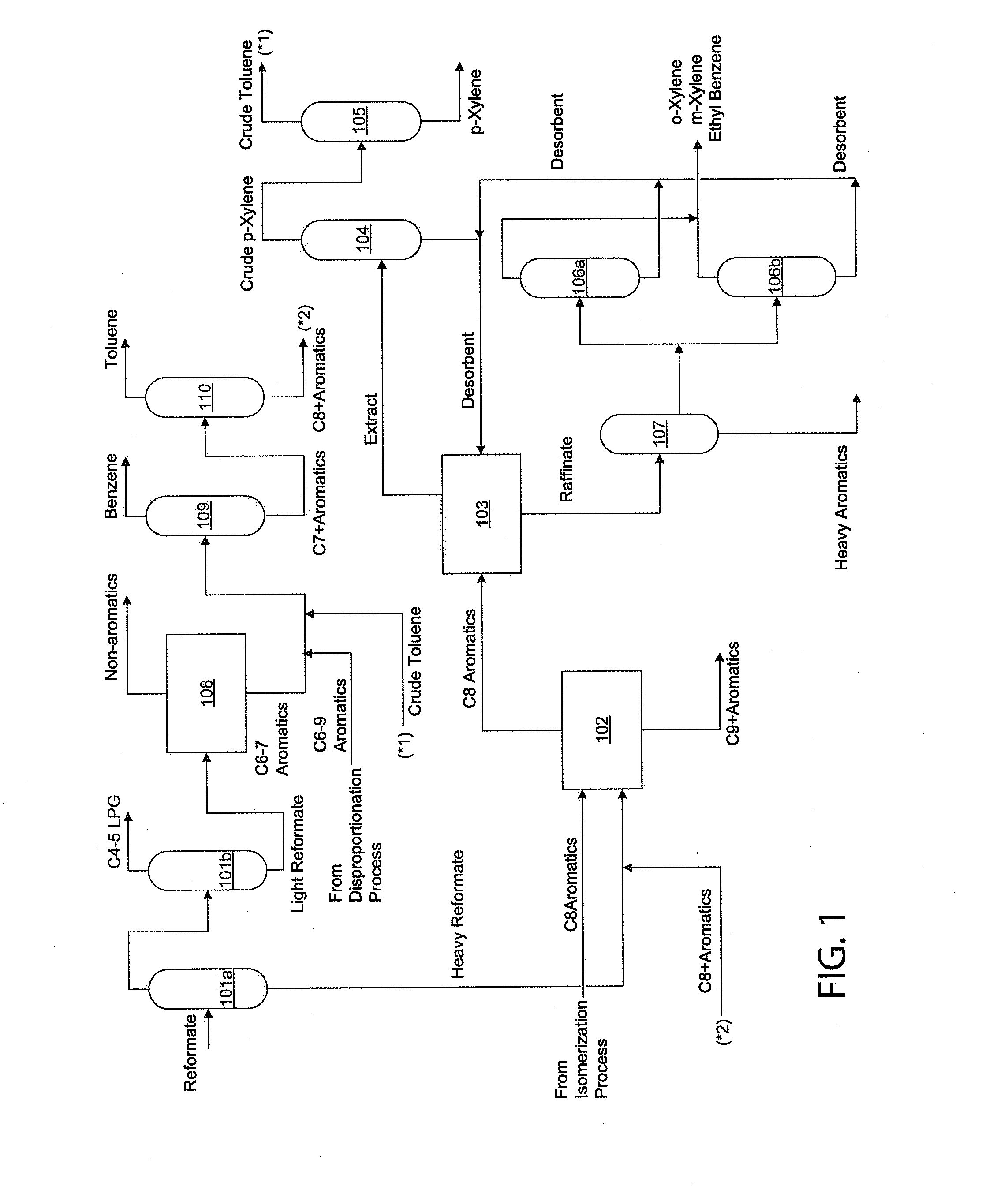
[0101]Furthermore, if the fourth distillation apparatus includes the low-pressure distillation column and the high-pressure distillation column (such as the low-pressure raffinate column 106a and the high-pressure raffinate column 106b shown in FIG. 1) as described before, the overhead vapor of the high-pressure distillation column (for example, the high-pressure raffinate column 106b) of the fourth distillation apparatus may be used as the “overhead vapor of the fourth distillation apparatus” to be used as a heat source of a reboiler.
[0102]Moreover, if the fourth distillation apparatus includes the low-pressure distillation column and the high-pressure distillation column, the overhead vapor of the high-pressure distillation column (for example, the high-pressure raffinate column 106b) of the fourth distillation apparatus may be used as a heat source of a reboiler provided for the low-pressure distillation column (for example, the low-pressure raffinate column 106a) of the fourth distillation apparatus.
[0103]If the aromatic hydrocarbon production apparatus includes the aromatics extraction apparatus, the sixth distillation apparatus and the seventh distillation apparatus (such as the aromatics extraction apparatus 108, the benzene column 109 and the toluene column 110 shown in FIG. 1), the aromatic hydrocarbon production apparatus may be configured so that the overhead vapor of the fourth distillation apparatus is used as a heat source of a reboiler provided for the seventh distillation apparatus. In this case, it is preferred that the fourth distillation apparatus is configured with a single distillation column, and that the overhead vapor of this single distillation column is used as the “overhead vapor of the fourth distillation apparatus”. However, even when the aromatic hydrocarbon production apparatus includes the aromatics extraction apparatus, the sixth distillation apparatus and the seventh distillation apparatus, the fourth distillation apparatus may include the low-pressure distillation column and the high-pressure distillation column as described above, and the overhead vapor of this high-pressure distillation column may be used as the “overhead vapor of the fourth distillation apparatus”.

Problems solved by technology

Distillation is a unit operation that consumes large energy, and energy consumption is large in production of aromatic hydrocarbons.
Since energy necessary for the xylene column per se is essentially large, however, even if the energy is saved by using the overhead vapor of the xylene column as the heat source of a reboiler of another distillation column without reducing the energy necessary for the xylene column per se, there is a limit in reducing the energy consumption of the whole process.

Method used


Image

  • Aromatic hydrocarbon production apparatus
  • Aromatic hydrocarbon production apparatus
  • Aromatic hydrocarbon production apparatus

Examples


example 1

[0249]FIG. 3 shows a process flow and operation conditions (temperatures, pressures and heat duties) employed in Example 1. A low-pressure reformate splitter 101a is operated at a pressure of 150 kPaA, uses overhead vapor of a high-pressure raffinate column 106b as a part of the heat source of its reboiler and uses medium-pressure steam as the rest of the heat source. A high-pressure reformate splitter 101b is operated at a pressure of 350 kPaA and uses low-pressure steam as the heat source of its reboiler.

[0250]As a xylene column, a HIDiC including a low-pressure xylene column 102a and a high-pressure xylene column 102b is applied. The low-pressure xylene column is operated at a pressure of 170 kPaA and uses high-pressure steam as the heat source of a reboiler provided therein. The high-pressure xylene column is operated at a pressure of 370 kPaA. For effecting internal heat exchange between the low-pressure xylene column (particularly, a stripping section included in the low-press...

example 2

[0273]FIG. 4 shows a process flow and operation conditions (temperatures, pressures and heat duties) of Example 2. In this example, a process flow that can further reduce the total energy consumption as compared with that attained in Example 1 was constructed, by changing the heat sources of the reboilers of a benzene column and a toluene column. Specifically, the operation pressure of the toluene column was changed, and the overhead vapor of a high-pressure raffinate column was used as the heat source of the reboiler of the toluene column. Since the heat duty of the multiple effect increased, a distribution amount of the raffinate to the high-pressure raffinate column was increased for adjustment. As a result, it was found that the reduction of the total energy consumption attained by providing a low-pressure raffinate column was reduced. Therefore, from the viewpoint of the reduction of investment cost, the low-pressure raffinate column used in Example 1 is not provided, and the h...


PUM

PropertyMeasurementUnit
saturation temperatureaaaaaaaaaa
temperatureaaaaaaaaaa

Abstract

An apparatus includes a first distillation apparatus for obtaining a fraction enriched in C8+ aromatics; a second distillation apparatus for obtaining a fraction enriched in C8 aromatics; an adsorption separation apparatus for obtaining an extract containing para-xylene and a raffinate containing xylene isomers; a third distillation apparatus for obtaining a fraction enriched in para-xylene; and a fourth distillation apparatus for obtaining a fraction enriched in xylene isomers. The second distillation apparatus includes a high-pressure part including a rectifying section; a low-pressure part including a stripping section; a line for directing overhead vapor of the low-pressure part to a column bottom of the high-pressure part; a line for directing a column bottom liquid of the high-pressure part to a column top of the low-pressure part; and a heat exchange structure for transferring heat from the rectifying section to the stripping section.

Description

[0001]This application is based upon and claims the benefit of priority from Japanese patent application No. 2012-251952, filed on Nov. 16, 2012, the disclosure of which is incorporated herein in its entirety by reference.BACKGROUND OF THE INVENTION[0002]1. Field of the Invention[0003]The present invention relates to an aromatic hydrocarbon production apparatus for obtaining aromatic hydrocarbons from a feedstock, such as reformate, containing aromatic hydrocarbons.[0004]2. Description of the Related Art[0005]Among aromatic hydrocarbons, benzene and xylene are significant basic chemicals used as raw materials for various industrial products. Benzene is mainly used for styrene monomer derivatives serving as raw materials for polystyrene or an ABS resin. Para-xylene, amongst xylenes, is used as a raw material for polyester fiber / resin and is one of basic chemicals in greatest demand.[0006]An aromatic hydrocarbon production apparatus (also referred to as an aromatics complex) includes ...

Claims


Application Information

Patent Timeline
Patent Type & Authority Applications(United States)
IPC IPC(8): C07C7/00B01D3/14
CPCB01D3/007B01D3/14B01D3/143B01D3/146C07C7/005C10G7/00C10G21/00C10G25/00C10G2300/1096C07C15/08B01J8/18C07C7/06
Inventor IO, SHOUTAWAKABAYASHI, TOSHIHIRO
Owner TOYO ENG CORP
Why Eureka
Try Eureka