
Automated Fluid Delivery Catheter and System

a fluid delivery and automatic technology, applied in the field of blood clearing devices, can solve the problems of less likely adoption of imaging modalities as a standard of care, difficult to maintain a constant flow of fluid through the small diameter of the catheter, and inability to achieve optimal treatment, so as to achieve the effect of increasing the pressure of the fluid flowing

Inactive Publication Date: 2014-05-22
LIGHTLAB IMAGING
View PDF3 Cites 68 Cited by
  • Summary
  • Abstract
  • Description
  • Claims
  • Application Information

AI Technical Summary

Benefits of technology

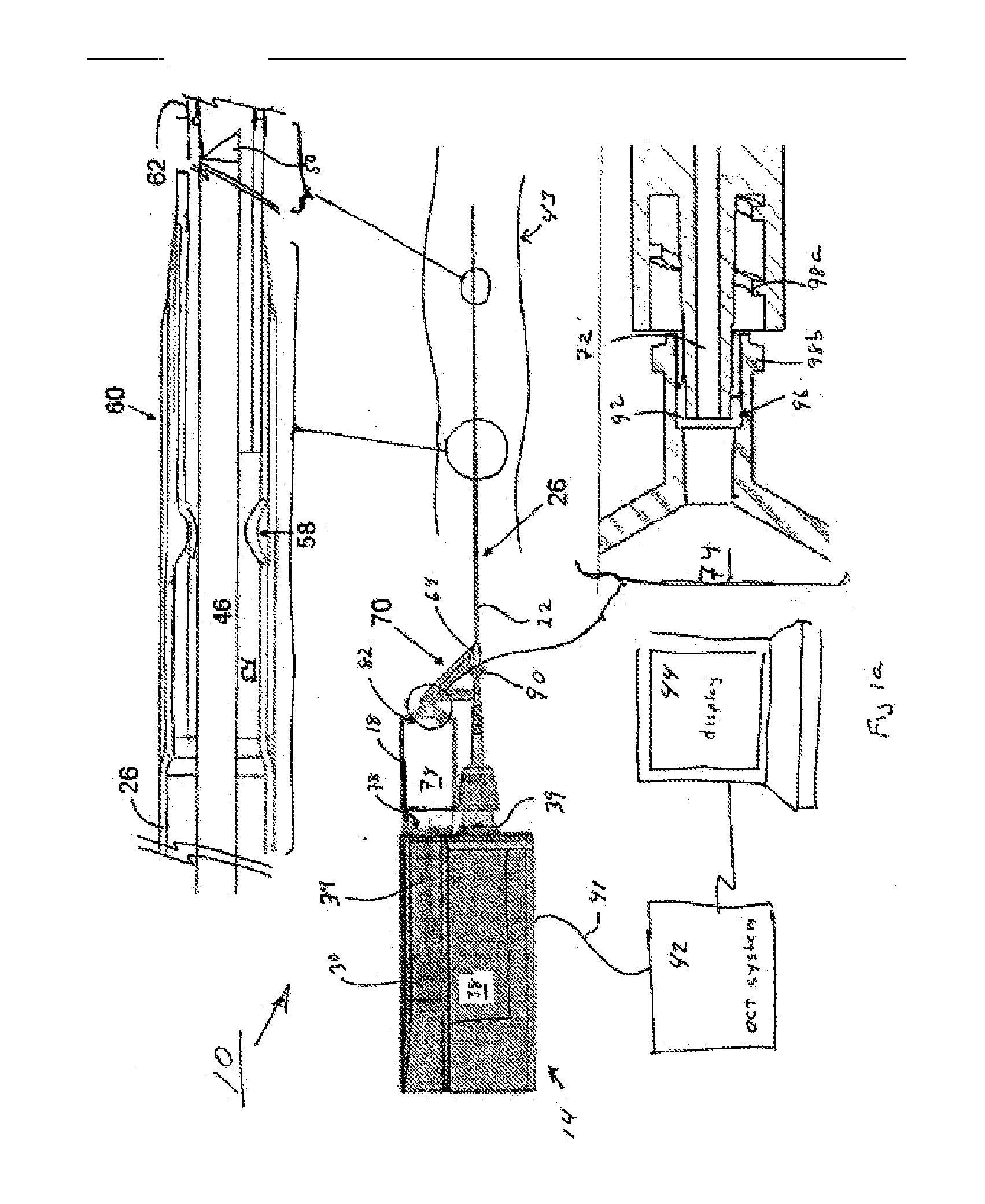
The invention is related to an optical coherence tomography system and a catheter for clearing blood in a vessel. The system includes a data collection probe with a rotating optical fiber and a pump for moving fluid from a fluid cartridge to the probe. The catheter has a wall with a flush port and a valve for controlling the flow of fluid. The control system can signal the pump to stop pumping if there is insufficient fluid in the cartridge. The catheter can also have a purge port for displacing air from the lumen. The method includes triggering a purge to remove air, passing a flush solution through the lumen, and collecting optical coherence tomography data during a pullback of the optical fiber. The invention provides improved optical coherence tomography data collection and blood vessel clearing.

Problems solved by technology

However, maintaining a constant flow of fluid through the small diameter of the catheter while imaging a section of a blood vessel is difficult.
Adding to the difficulty is the fact that assembling all the components used to flush a lumen takes time and makes the use of imaging modalities less likely to be adopted as a standard of care.
Unfortunately, the lack of vessel information may result in sub-optimal treatments.
However, many of these require a significant amount of set up time and sufficient strength and dexterity on the part of the clinician or operator.

Method used


Image

  • Automated Fluid Delivery Catheter and System
  • Automated Fluid Delivery Catheter and System
  • Automated Fluid Delivery Catheter and System

Examples


Embodiment Construction

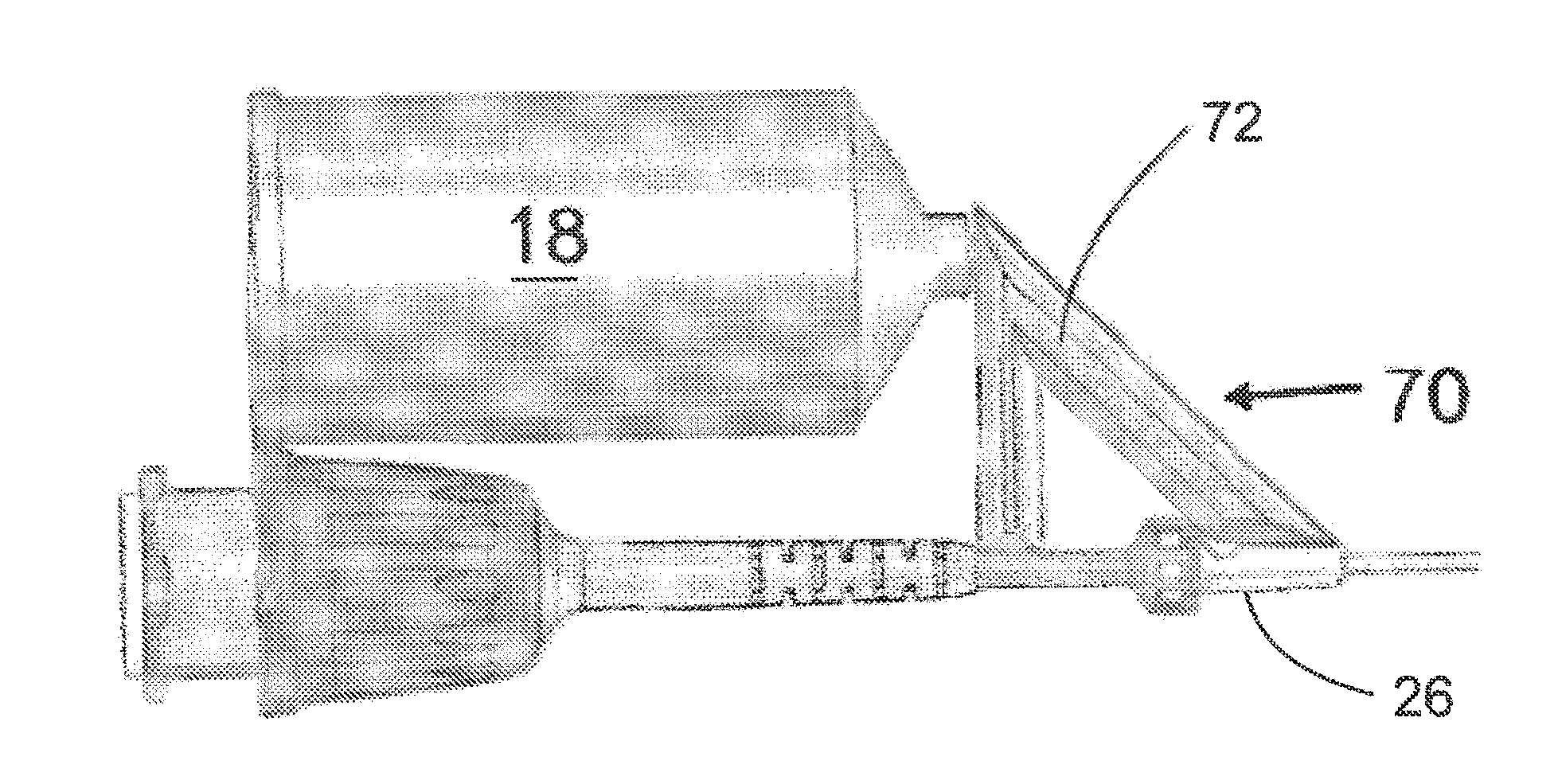
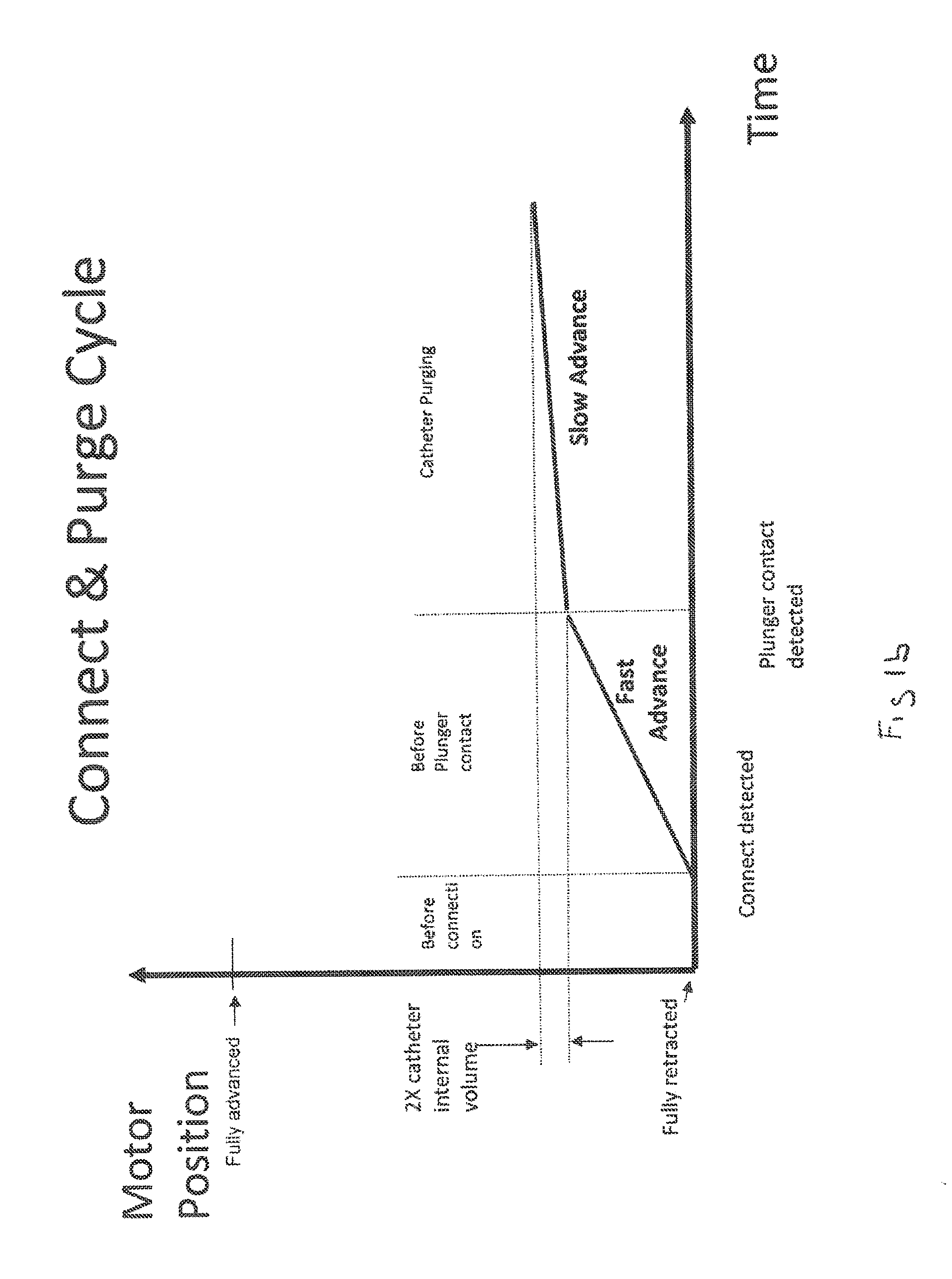
[0030]When OCT data is collected in a blood vessel, blood is initially dispersed around the probe that is used to collect data. An OCT scan in the presence of a blood field can result in the blood being misinterpreted as tissue. In part, this can occur because of the optical and interferometric nature of OCT. Therefore, it is desirable to clear blood from a blood vessel to improve the images of the vessel generated using data collected using an OCT probe. In one embodiment, a flush is used to clear a region of the blood vessel so that OCT imaging can be performed. Sections of the OCT probe can also have air disposed therein which is purged using a suitable solution prior to use in a subject. In part, embodiments of the invention relate to port placements, catheter configurations, flush and purge systems, components of the foregoing and related methods to expedite a given purge and / or flush procedure.

[0031]Various conveniences and devices for performing flushing and purging as part o...


PUM


Abstract

In part, the invention relates to catheters, methods, and blood clearing technologies suitable for use in an optical coherence tomography system. The optical coherence tomography system includes a control system, a probe including a catheter defining a lumen and a rotatable optical fiber located within the lumen, a fluid cartridge holder in communication with the lumen of the probe, a pump to move fluid from the fluid cartridge to the lumen of the probe; and a motor configured to rotate and pull the optical fiber through the lumen of a blood vessel. The pump and the motor are controlled by the control system. The catheter can include a wall that bounds the lumen of the probe, which defines a flush port and includes a valve in fluid communication with the flush port, the valve configured to permit fluid from the lumen to pass through the wall.

Description

CROSS-REFERENCE TO RELATED APPLICATIONS[0001]This application claims priority to and the benefit of U.S. Provisional Patent Application No. 61 / 727,320, filed on Nov. 16, 2012, the entire disclosure of which is herein incorporated by reference.FIELD OF THE INVENTION[0002]In part, the invention relates generally to blood clearing devices, related methods, components, and materials suitable for use with imaging systems such as optical coherence tomography data collection systems.BACKGROUND OF THE INVENTION[0003]A probe used for optical coherence tomography (OCT) and other blood vessel intraluminal imaging modalities typically includes a catheter having a lumen constructed for use with an optical fiber. During imaging, the optical fiber is rotated within the lumen. Light from a light source is transmitted through the optical fiber, leaving the optical fiber at its distal end and passing through the optical catheter wall. As the optical fiber rotates, the light beam from the optical fibe...

Claims


Application Information

Patent Timeline
Patent Type & Authority Applications(United States)
IPC IPC(8): A61M25/00A61B5/00
CPCA61B5/6852A61B8/12A61B5/0066A61B5/0215A61M2025/0035A61M39/10A61M2025/0024A61M39/24A61M2039/242A61B5/0073
Inventor PETROFF, CHRISTOPHER
Owner LIGHTLAB IMAGING
Learn More