Laminoplasty system

a laminoplasty and cervical stenosis technology, applied in the field of surgical procedures, can solve the problems of reducing the space available for nerve roots within the spinal canal, causing pain, weakness, or loss of feeling in the patient, and forming osteophytes (bone spurs)

Active Publication Date: 2014-05-22
SPECTRUM SPINE IP HLDG
View PDF2 Cites 5 Cited by
  • Summary
  • Abstract
  • Description
  • Claims
  • Application Information

AI Technical Summary

Benefits of technology

[0012]In another aspect, the lamina portion is controllably elevated to a relief position in which the spinal canal of the desired cervical vertebra has a relief cross-sectional area that is greater than the pre-operative cross-sectional area, wherein the lamina portion is subsequently secured in an

Problems solved by technology

In addition, spinal stenosis can result when bones and joints are enlarged, leading to the formation of osteophytes (bone spurs).
A significant cause of osteophytes is spondylosis, in which spinal discs lose water and become less dense.
Finally, diseased bone or tumors can extend into the spinal cord area, decreasing the space available for nerve roots within the spinal canal.
Compression of the spinal cord resulting from spinal stenosis can produce pain, weakness, or loss of feeling in the patient.
Additionally, spinal cord compression can lead to myelopathy, which causes neurological damage and results in spinal cord malfunction.
If left untreated, the compression can eventually damage the circulatory system within the spinal cord, leading to more severe myelopathy.
Due to the removal of portions of the supporting structures at the posterior of the vertebra that are used to align the spinal column, a laminectomy can create postural deformities in patients.
In addition, there is a risk that the procedure will lead to substantial scar formation in the patient.
However, this may lead to a decrease in the range of motion in the spine, and there may also be accelerated degeneration of the vertebrae above and below the repaired vertebra.
Despite the advances that have been achieved in laminoplasty procedures, there are still some limitations in the effectiveness of the procedures and the ease with which the procedures are completed, especially when performed on the cervical vertebrae.
For example, the present technique requires the surg

Method used


Image

  • Laminoplasty system
  • Laminoplasty system
  • Laminoplasty system

Examples


Embodiment Construction

[0029]The present invention can be understood more readily by reference to the following detailed description, examples, and claims, and their previous and following description. Before the present system, devices, and / or methods are disclosed and described, it is to be understood that this invention is not limited to the specific systems, devices, and / or methods disclosed unless otherwise specified, as such can, of course, vary. It is also to be understood that the terminology used herein is for the purpose of describing particular aspects only and is not intended to be limiting.

[0030]The following description of the invention is provided as an enabling teaching of the invention in its best, currently known aspect. Those skilled in the relevant art will recognize that many changes can be made to the aspects described, while still obtaining the beneficial results of the present invention. It will also be apparent that some of the desired benefits of the present invention can be obta...


PUM


Abstract

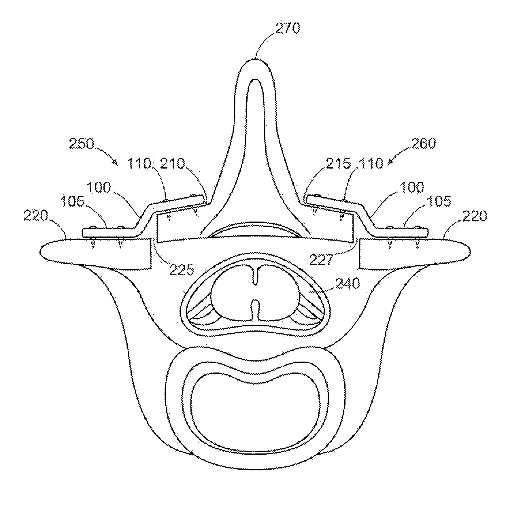
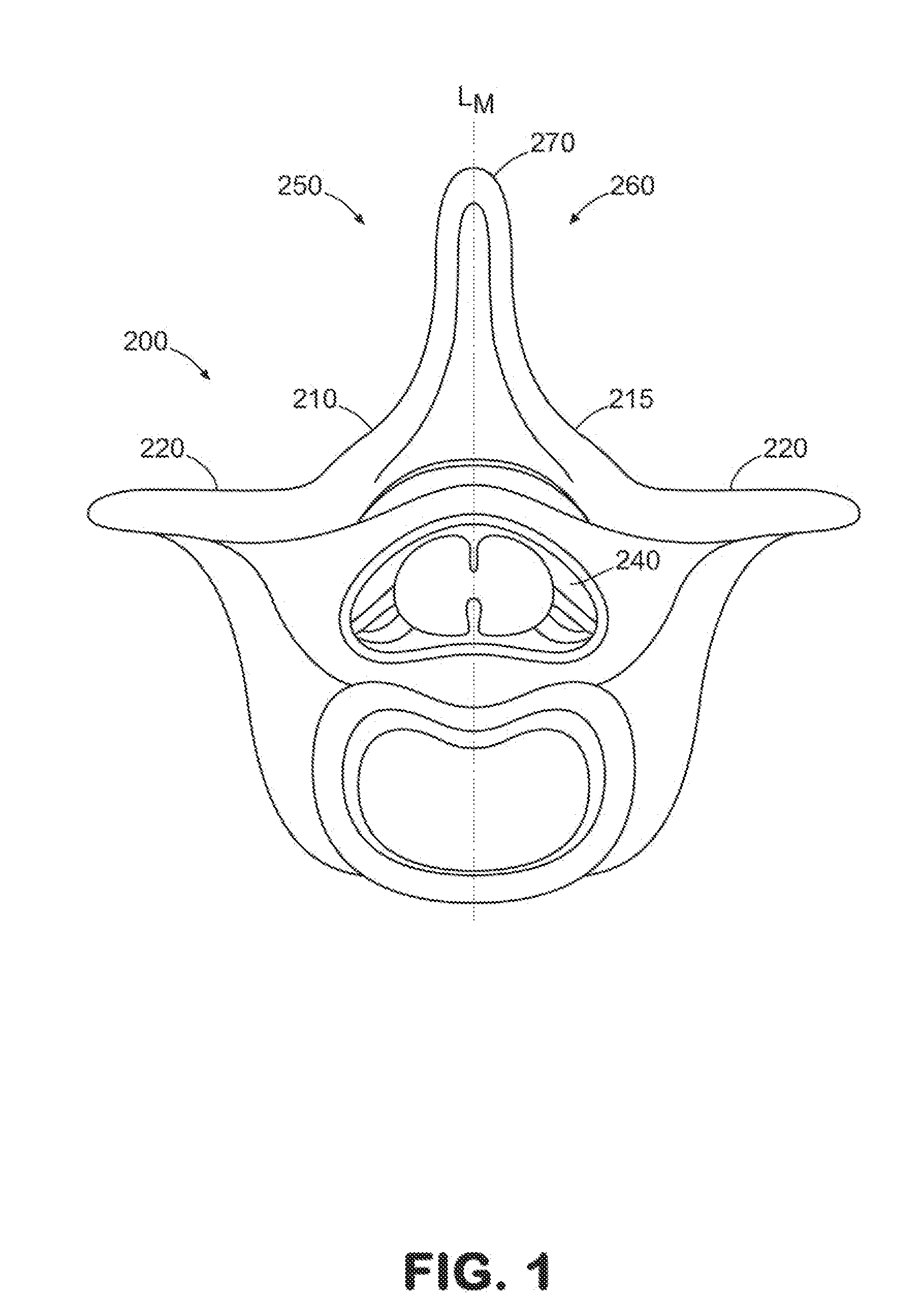
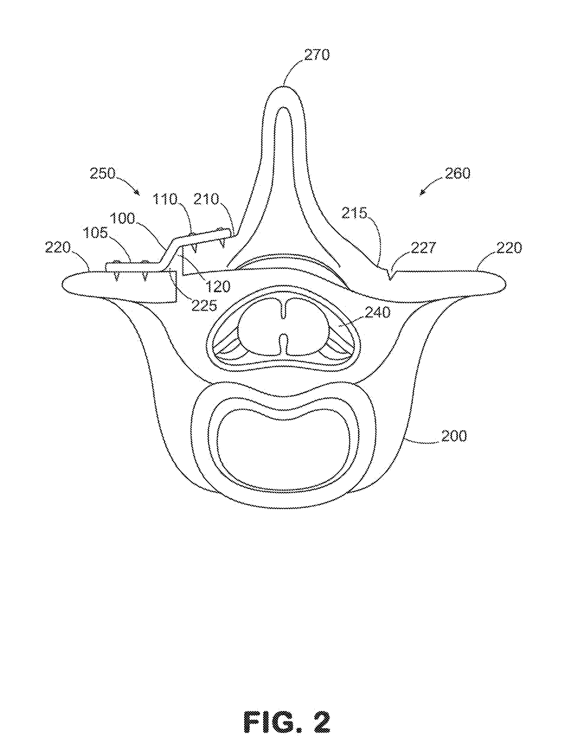
A laminoplasty plate for securing a separated lamina portion of a desired cervical vertebra in a relief position and a method of using the same to perform a laminoplasty. In one aspect, a lamina setting tool is presented for positioning the lamina portion of the desired cervical vertebra in the relief position. In one aspect, the tool has a first sidewall section that slides in longitudinal relation to a second sidewall section.

Description

FIELD OF THE INVENTION[0001]The present invention relates generally to surgical procedures, most particularly for use in performing a laminoplasty to treat cervical stenosis in the spine. More specifically, the invention pertains to a method for increasing the area of the spinal canal by securing a separated lamina portion of a desired cervical vertebra in a relief position.BACKGROUND OF THE INVENTION[0002]Spinal stenosis is a pathology of the spine that involves the narrowing of the spinal canal, through which the spinal cord and nerve roots run. This narrowing may be congenital and, consequently, can affect patients at any age. Spinal stenosis may result from thickening and calcification of spinal ligaments. For example, calcification can result from deposits of calcium salts within the spine. In addition, spinal stenosis can result when bones and joints are enlarged, leading to the formation of osteophytes (bone spurs). A significant cause of osteophytes is spondylosis, in which ...

Claims


Application Information

Patent Timeline
IPC IPC(8): A61B17/70A61B17/80
CPCA61B17/7071A61B17/808
Inventor ROBINSON, JAMES C.
Owner SPECTRUM SPINE IP HLDG
Why Eureka
Try Eureka