Brushless doubly fed machines

US20140145541A1Inactive Publication Date: 2014-05-29WIND TECH

Image

  • Brushless doubly fed machines
  • Brushless doubly fed machines
  • Brushless doubly fed machines

Examples


Embodiment Construction

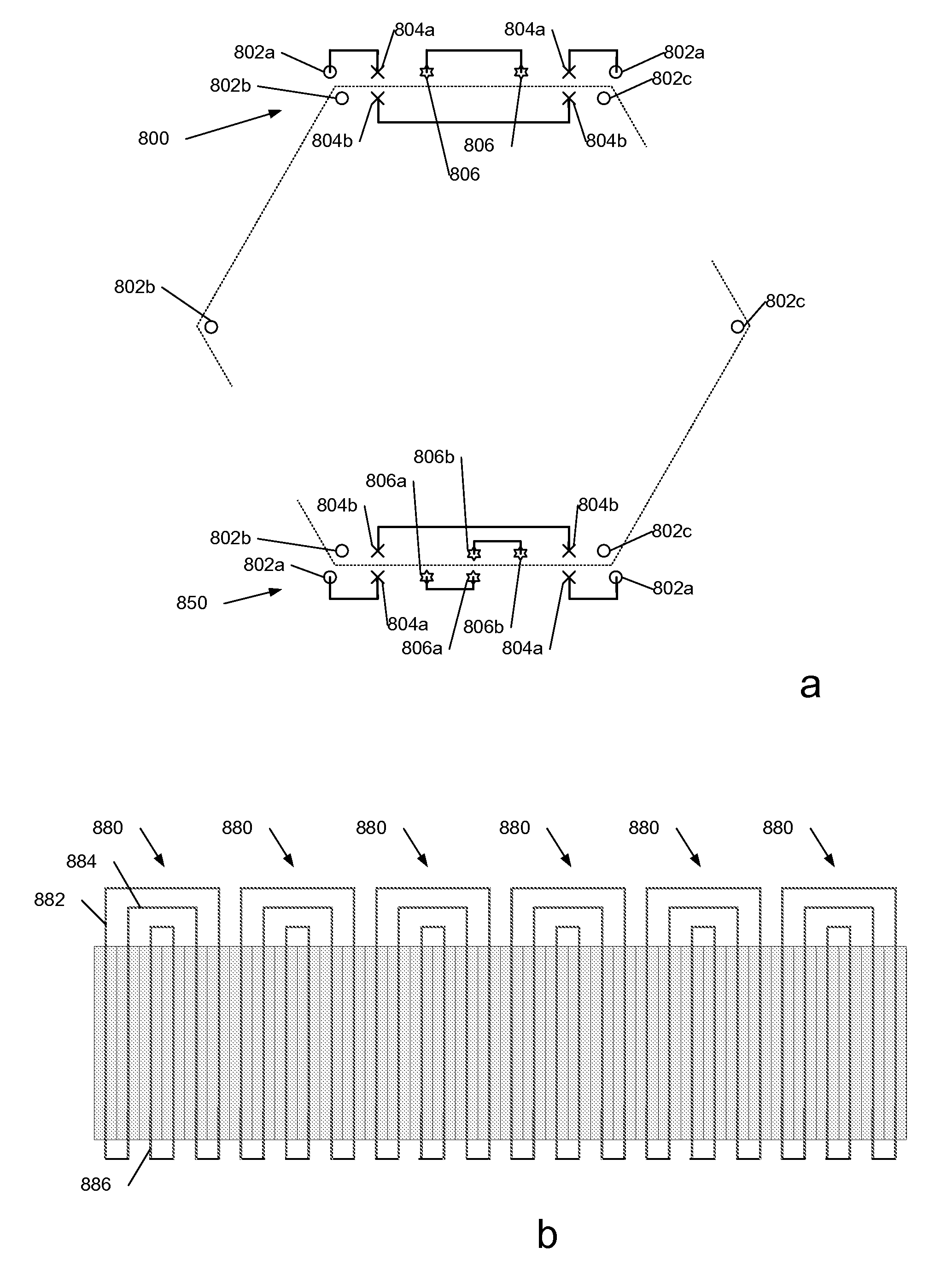
[0026]With copper-efficient BDFM rotor designs, such as the widely used nested loop configuration, harmonics of the two principal fields are generated at higher levels than found in conventional machine windings. For example the pitching of loops in the nested loop design leads to a substantial harmonic content in the air-gap. This will be reflected in an increase in leakage inductance of the rotor but couplings via harmonics to other loops and the stator windings will damp the amplitude of the harmonic fields to a degree. Also as machine size increases, the cross-section of the bars in a nested loop rotor will also increase, notwithstanding the greater number of rotor slots. A concern then arises about the skin effect, especially as the frequency of rotor currents will be a substantial fraction of the grid frequency. Under these conditions multiple conductors in each slot become desirable, and multilayer windings, such as the progressive loop winding in which a number of coils of e...


PUM


Abstract

We describe a brushless doubly fed machine (BDFM) comprising a stator having first and second sets of poles with p1, p2 respective numbers of pole pairs, and a rotor having (p1+p2) sets of electrically conducting loops. Each loop comprises a pair of conducting elements extending longitudinally along a direction of rotation of said rotor. Each said set of electrically conducting loops comprises at least first and second loops electrically connected in series with one another and at least one third loop configured to form a parallel load on said stator. An area encompassed by said third loop is less than an area encompassed by either of said first and second loops. Embodiments of this rotor design efficiently couple to two stator magnetic fields and suppress a space harmonic field.

Description

FIELD OF THE INVENTION[0001]This invention relates to improved brushless doubly fed machines (BDFMs), which here includes brushless doubly fed induction generators (BDFIGs). More particularly the invention relates to improved rotor designs for such machines.BACKGROUND TO THE INVENTION[0002]The generation of electricity from the wind is a proven means of obtaining energy without the emission of carbon dioxide. Wind turbines range from large machines with peak outputs of several Megawatts to small machines designed for domestic use. The most commonly used generator, at least in larger wind turbines, employs a wound rotor induction machine with a double feed. The rotor of the machine is wound with three-phase windings and connections are made to them by slip rings. In large wind turbines, a gearbox is generally used to increase the shaft speed at the blades, say 50 rpm, typically to 1000 to 1500 rpm to allow a 4 pole or 6 pole generator to be used. These are relative compact machines b...

Claims


Application Information

Patent Timeline
29 May 2014
Publication
US20140145541A1
IPC
H02K3/28; H02K17/42
CPC
H02K17/36; H02K2213/03; H02K2213/09; Y02E10/72; H02K3/28; H02K17/42
Inventors
JALEBI, EHSAN ABDI; MCMAHON, RICHARD ANTHONY