Arrangements and methods for triac dimming of gas discharge lamps powered by electronic ballasts

Inactive Publication Date: 2014-05-29
LUCIDITY LIGHTS
View PDF7 Cites 23 Cited by
  • Summary
  • Abstract
  • Description
  • Claims
  • Application Information

AI Technical Summary

Benefits of technology

[0011]In accordance with an exemplary and non-limiting embodiment, a method for dimming a gas discharge lamp with a wall dimmer is provided. The method may provide uninterruptible operation of the lamp and the ballast during TRIAC dimming. The method may include powering the ballast without electrolytic smoothing capacitor, directly from rectified AC voltage that is chopped by the TRIAC dimmer and supporting lamp operation during off time

Problems solved by technology

But wall dimmers are not capable of dimming a regular single stage ballast.
Since conduction angle of bridge rectifier is very short and holding current is not provided during the rest of the period, the TRIAC operation becomes unstable and causes lamp flickering.
But steady power losses in the resistor could be significant.
Power consumption during starting interval of the ballast could be up to 80 W because of the high power losses in the lamp and the ballast.
Therefore, the dimming method illustrated in FIG. 2 is not practical because of high power stresses applied to both lamp and ballast.
But unfortunately, injecting RF power in front end 60 Hz

Method used


Image

  • Arrangements and methods for triac dimming of gas discharge lamps powered by electronic ballasts
  • Arrangements and methods for triac dimming of gas discharge lamps powered by electronic ballasts
  • Arrangements and methods for triac dimming of gas discharge lamps powered by electronic ballasts

Examples


Example

[0024]While described in connection with certain exemplary and non-limiting embodiments, other exemplary embodiments would be understood by one of ordinary skill in the art and are encompassed herein. It is therefore understood that, as used herein, all references to an “embodiment” or “embodiments” refer to an exemplary and non-limiting embodiment or embodiments, respectively.

DETAILED DESCRIPTION

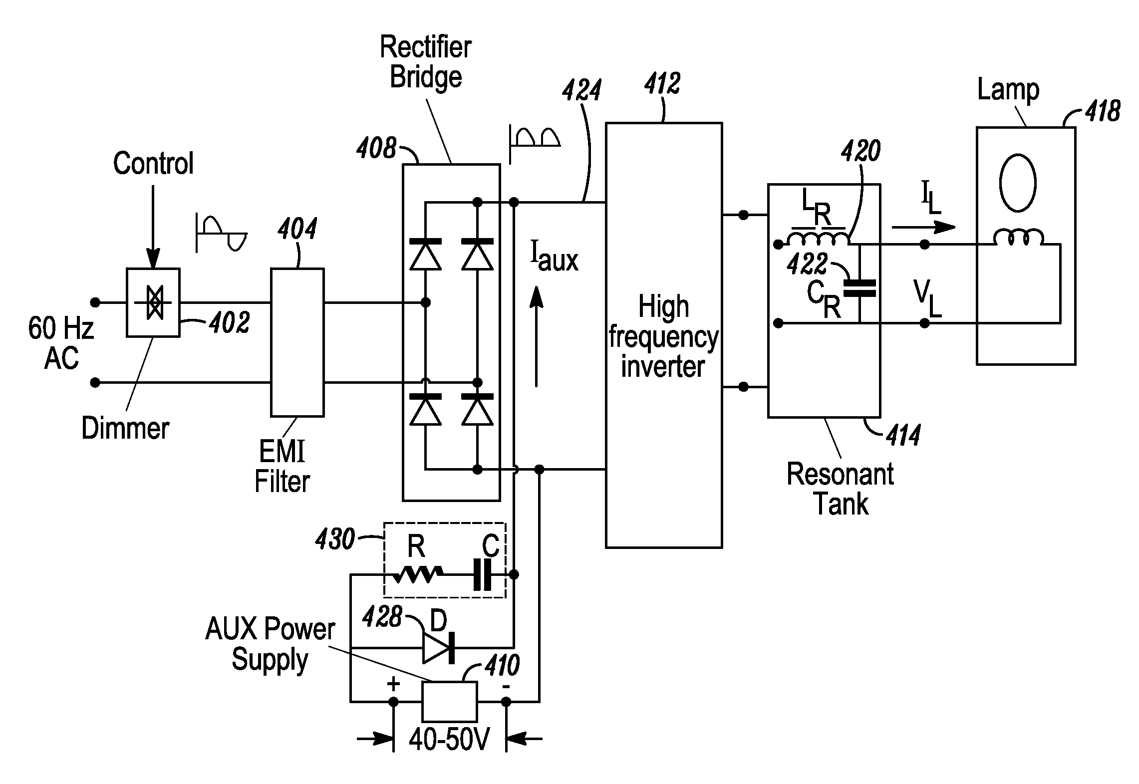
[0025]FIG. 4 shows block-circuit diagram of an electronic ballast connected to a TRIAC dimmer 402. The dimmer 402 may be for instance, a wall dimmer aimed for controlling incandescent lamps. The electronic ballast may feature a front-end power supply without a traditional smoothing capacitor, such as with a smoothing electrolytic capacitor-less D.C. bus. It may comprise an EMI filter 404, a Bridge Rectifier 408, a high frequency Inverter 412 (e.g. a 2.5 MHz inverter), and resonant load that includes Resonant Tank 414 and electrodeless Lamp 418. In accordance with exemplary and non-limiting ...


PUM


Abstract

An apparatus for powering and TRIAC dimming of a gas discharge lamp includes an electronic ballast for powering a gas discharge lamp from a TRIAC based dimmer connected to an AC line, an EMI filter for protecting the AC line from EMI generated by the ballast and the lamp, a DC bus without a smoothing electrolytic capacitor, a resonant DC-to-AC inverter connected to the DC bus for powering the gas discharge lamp with a high frequency current, wherein an auxiliary DC-to-DC power supply input is connected to the DC bus and a first resonant tank having in series a first resonant inductor and a first resonant capacitor, wherein the gas discharge lamp is connected in parallel to the resonant capacitor.

Description

BACKGROUND[0001]1. Field[0002]This invention relates to electronic ballasts, and more particularly for single stage ballasts and TRIAC dimmable high frequency electrodeless lamps.[0003]2. Description of Related Art[0004]Phase controlled TRIAC dimmers are commonly used for dimming incandescent lamps. TRIAC is a bidirectional gate controlled switch that may be incorporated in a wall dimmer. A typical dimmer circuit with an incandescent lamp is shown in FIG. 1, where the TRIAC turns “on” every half of AC period. The turn “on” angle is determined by the position of the dimmer potentiometer and can vary in range from 0 to 180 degrees. Typically the lighting dimmer is combined with a wall switch. An incandescent lamp is an ideal load for a TRIAC. It provides a sufficient latching and holding current for stable turn “on” state. The TRIAC returns to its “off” state position at the AC voltage zero crossing. But wall dimmers are not capable of dimming a regular single stage ballast. These bal...

Claims


Application Information

Patent Timeline
IPC IPC(8): H05B41/38
CPCH05B41/38H05B41/2806Y02B20/00
Inventor ALEXANDROV, FELIX I.LESTER, JAMES N.MAYA, JAKOB
Owner LUCIDITY LIGHTS
Why Eureka
Try Eureka