Thin film microbattery charge and output control

a microbattery and charge technology, applied in the direction of electric power, electric vehicles, transportation and packaging, etc., can solve the problems of increasing the impedence of the microbattery, and achieve the effect of prolonging the battery li

Active Publication Date: 2014-05-29
CYMBET CORP
View PDF12 Cites 10 Cited by
  • Summary
  • Abstract
  • Description
  • Claims
  • Application Information

AI Technical Summary

Benefits of technology

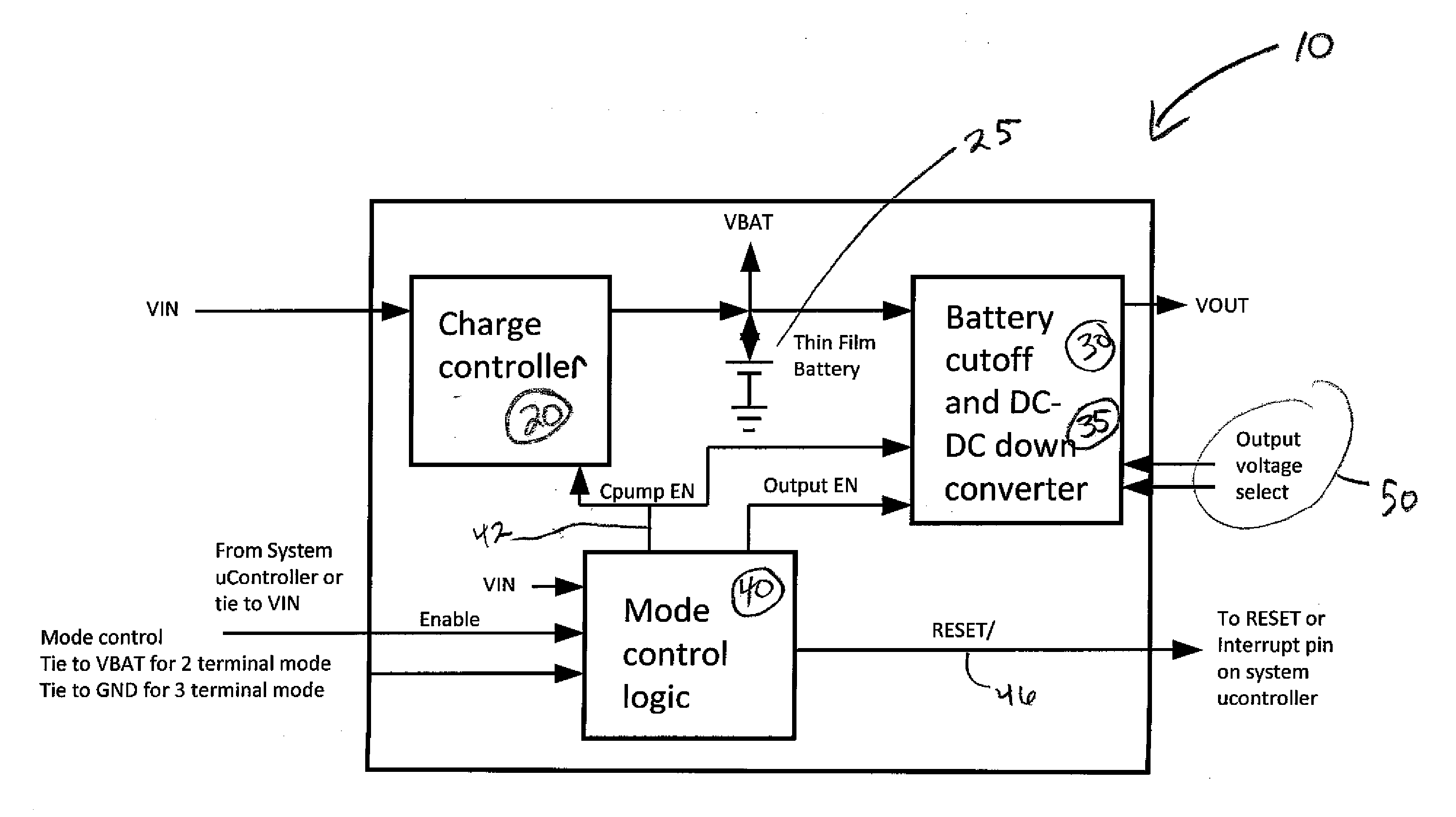
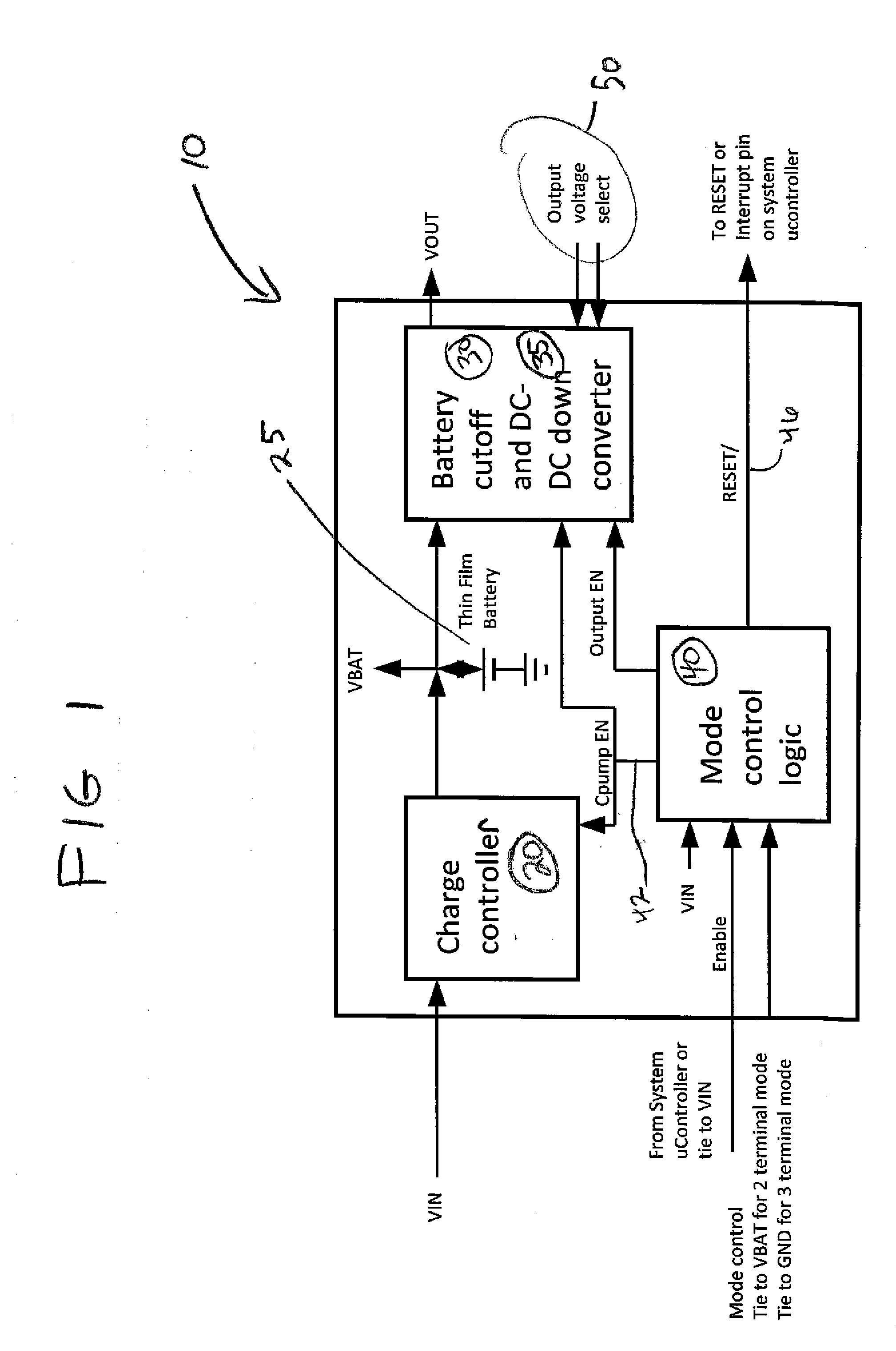
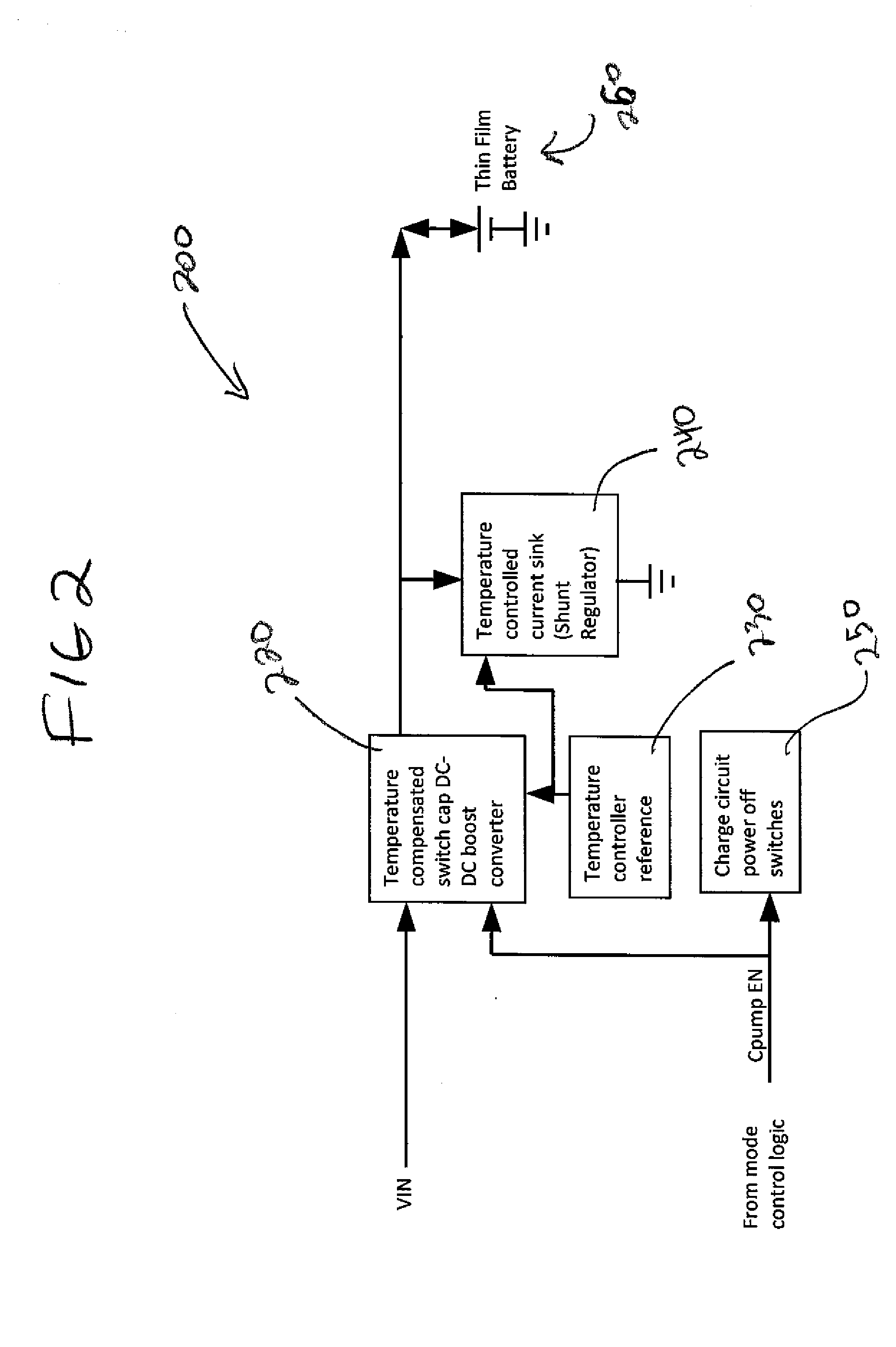
[0005]A control system is provided that controls both charge control and output control of a rechargeable thin film microbattery cell. The present system includes a charge control logic component configured to control the level of charge of a thin film microbattery cell. The charge control logic component thus protects and extends battery life. Additionally, a battery cut-off logic component is included to cease current draw on the thin battery thin film microbattery cell under predetermined conditions. A mode control logic component is operably coupled to the charge control logic component and the battery cut-off logic component to enable operation of the charge control logic component and the battery cut-off logic component under predetermined conditions.

Problems solved by technology

Similarly, as a microbattery is exposed to multiple cycles, the level of impedence of the microbattery increases.

Method used


Image

  • Thin film microbattery charge and output control
  • Thin film microbattery charge and output control
  • Thin film microbattery charge and output control

Examples


Embodiment Construction

[0017]It is to be understood that a device and method in accordance with the present invention includes, but is not limited to, novel combinations of conventional components, and not just particular detailed configurations thereof. Accordingly, the structure, methods, functions, control and arrangement of conventional components and circuits have, for the most part, been illustrated in the drawings by readily understandable block representations and schematic diagrams, in order not to obscure the disclosure with structural details which will be readily apparent to those skilled in the art, having the benefit of the description herein. Further, the invention is not limited to the particular embodiments depicted in the exemplary diagrams, but should be construed in accordance with the language in the claims.

[0018]For purposes of the present invention, a thin film microbattery cell is a microbattery cell having dimensions not exceeding a longest dimension of 60 mm, more preferably not ...


PUM


Abstract

A control system for charge and output control of a rechargeable thin film microbattery cell comprises a charge control logic component configured to control the level of charge of a thin film microbattery cell, a battery cut-off logic component to cease current draw on the thin battery thin film microbattery cell under predetermined conditions, a mode control logic component operably coupled to the charge control logic component and the battery cut-off logic component to enable operation of the charge control logic component and the battery cut-off logic component under predetermined conditions, and a Switch Capacitor DC-DC Downconverter Component for delivery of voltage external to the system configured to reduce battery output voltage potential by a factor of at least 2:1. Systems operably connected to a rechargeable thin film microbattery cell and powered devices comprising the system and the microbattery cell are also described.

Description

FIELD OF THE INVENTION[0001]This invention relates to the field of thin-film energy-storage devices, and more specifically to control of thin-film microbattery charge and output.BACKGROUND OF THE INVENTION[0002]Electronics have been incorporated into many portable devices such as computers, mobile phones, tracking systems, scanners, etc. One drawback to portable devices is the need to include the power supply with the device. Portable devices typically use batteries as power supplies. Batteries must have sufficient capacity to power the device for at least the length of time the device is in use. Sufficient battery capacity can result in a power supply that is quite heavy and / or large compared to the rest of the device. Accordingly, smaller and lighter batteries (i.e., power supplies) with sufficient energy storage are desired. Other energy storage devices, such as supercapacitors, and energy conversion devices, such as photovoltaics and fuel cells, are alternatives to batteries for...

Claims


Application Information

Patent Timeline
Patent Type & Authority Applications(United States)
IPC IPC(8): H02J7/00
CPCH02J7/007H02J7/007192
Inventor MULLIN, JEFFREY D.SATHER, JEFFREY S.
Owner CYMBET CORP
Why Eureka
Try Eureka