Backlight module and liquid crystal display device using same

a backlight module and liquid crystal display technology, applied in the field of backlight modules and liquid crystal display devices, can solve the problems of inability to restore the true color of objects, thin bezels, narrow color gamut, etc., and achieve the effect of effectively overcoming the firebug effect and reducing the manufacture cos

Active Publication Date: 2014-05-29
SHENZHEN CHINA STAR OPTOELECTRONICS TECH CO LTD
View PDF5 Cites 10 Cited by
  • Summary
  • Abstract
  • Description
  • Claims
  • Application Information

AI Technical Summary

Benefits of technology

[0007]An object of the present invention is to provide a backlight module, which uses sun light as a backlight source to effectively reduce the manufacture cost and provide homogeneous illumination and effectively overcome the firebug effect.

Problems solved by technology

In the conventional light source, LED or CCFL emits white light by mixing lights emitting from fluorescent powders, which renders color gamut narrow and color reproducibility poor, making it not able to restore the true color of an object.
However, increasing the light mixing distance needs to increase the thickness of the bezel and this affects the outside appearance of the liquid crystal display device.
Using a large number of optic fibers 700 would overcome the problem of firebug effect, but the increased number of optic fibers 700 between the light collector and the light incidence site would increase the cost, making it disadvantageous for cost control.

Method used


Image

  • Backlight module and liquid crystal display device using same
  • Backlight module and liquid crystal display device using same
  • Backlight module and liquid crystal display device using same

Examples


Embodiment Construction

[0032]To further expound the technical solution adopted in the present invention and the advantages thereof, a detailed description is given to a preferred embodiment of the present invention and the attached drawings.

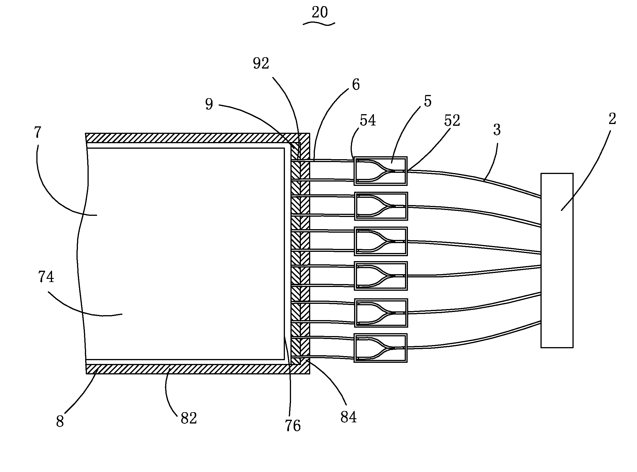
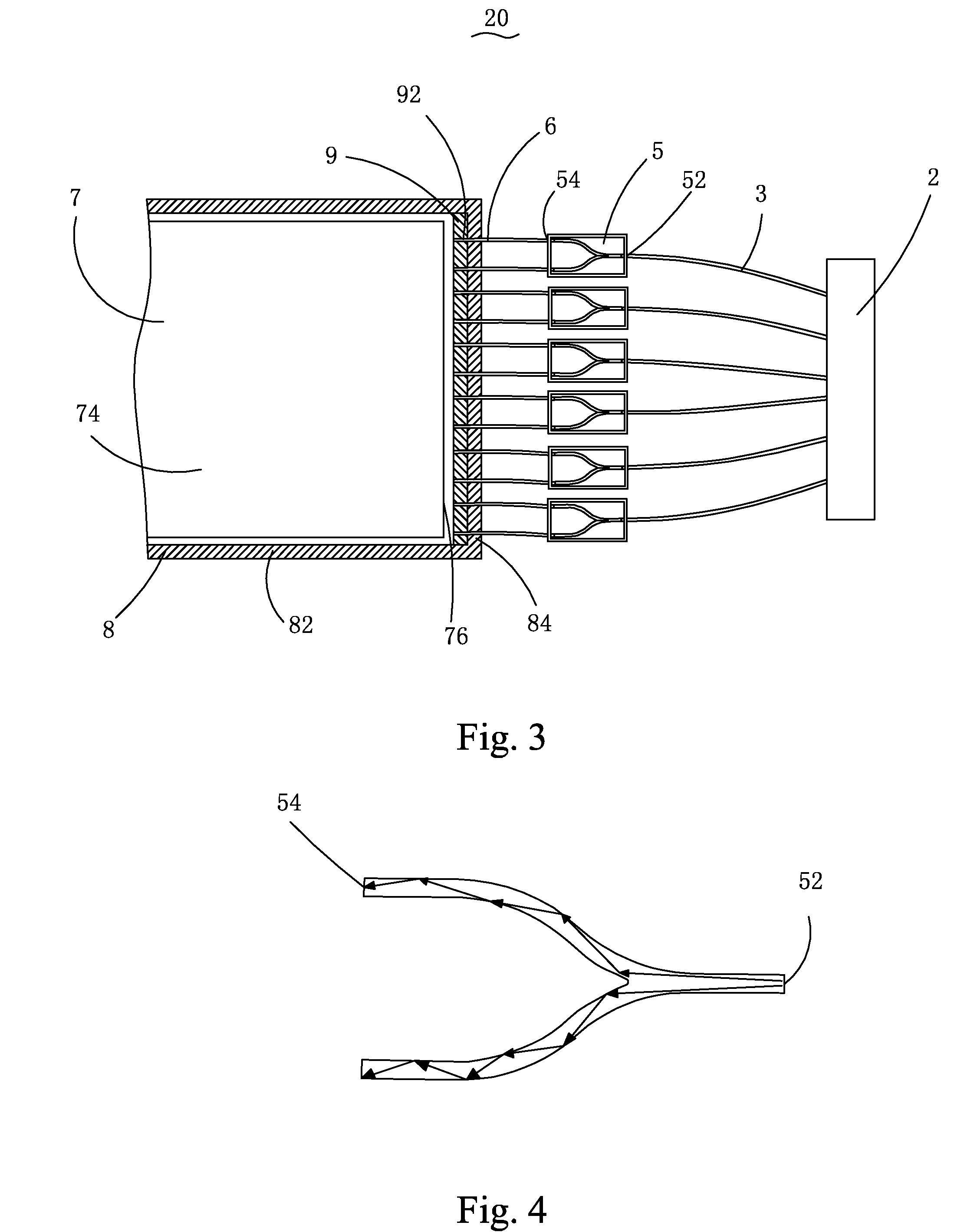
[0033]Referring to FIGS. 3 and 4, the present invention provides a backlight module 20, which comprises a light collector 2, a plurality of first optical fibers 3 connected to the light collector 2, a plurality of first optical fiber splitters 5 connected to the first optical fibers 3, a plurality of second optic fibers 6 connected to the first optical fiber splitters 5, and a light guide plate 7 arranged at one side of the second optic fibers 6. Each of the first optical fiber splitters 5 comprises a first light inlet 52 and a plurality of first light outlets 54. The first light inlets 52 are respectively connected to the first optical fibers 3. The first light outlets 54 are respectively connected to the second optic fibers 6. The light collector 2 receives and colle...


PUM

PropertyMeasurementUnit
color reproducibilityaaaaaaaaaa
color integrityaaaaaaaaaa
distanceaaaaaaaaaa

Abstract

The present invention provides a backlight module and a liquid crystal display device using the backlight module. The backlight module includes a light collector, a plurality of first optical fibers connected to the light collector, a plurality of first optical fiber splitters connected to the first optical fibers, a plurality of second optic fibers connected to the first optical fiber splitters, and a light guide plate arranged at one side of the second optic fibers. Each of the first optical fiber splitters includes a first light inlet and a plurality of first light outlets. The first light inlets are respectively connected to the first optical fibers and the first light outlets are respectively connected to the second optic fibers. The backlight module uses optic fiber splitters to split received sun light for making dense and uniform distribution of sun light at a light incidence site of a light guide plate.

Description

BACKGROUND OF THE INVENTION[0001]1. Field of the Invention[0002]The present invention relates to the field of liquid crystal displaying, and in particular to a backlight module and a liquid crystal display device using the backlight module.[0003]2. The Related Arts[0004]Liquid crystal display (LCD) has a variety of advantages, such as thin device body, low power consumption, and being free of radiation, and is thus widely used. Most of the LCDs that are currently available in the market are backlighting LCDs, which comprise a liquid crystal panel and a backlight module. The operation principle of the liquid crystal panel is that liquid crystal molecules are interposed between two parallel glass substrates and the liquid crystal molecules are controlled to change direction by application of electricity to the glass substrates in order to refract out light emitting from the backlight module for generating images. Since the liquid crystal panel itself does not emit light, light must be...

Claims


Application Information

Patent Timeline
Patent Type & Authority Applications(United States)
IPC IPC(8): G02F1/1335G02B6/04
CPCG02B6/04G02F1/133606G02B6/0028G02F1/133615G02F1/133308G02F1/133314
Inventor LI, DEHUACHEN, SHIHHSIANGCHEN, LIYI
Owner SHENZHEN CHINA STAR OPTOELECTRONICS TECH CO LTD
Why Eureka
Try Eureka