

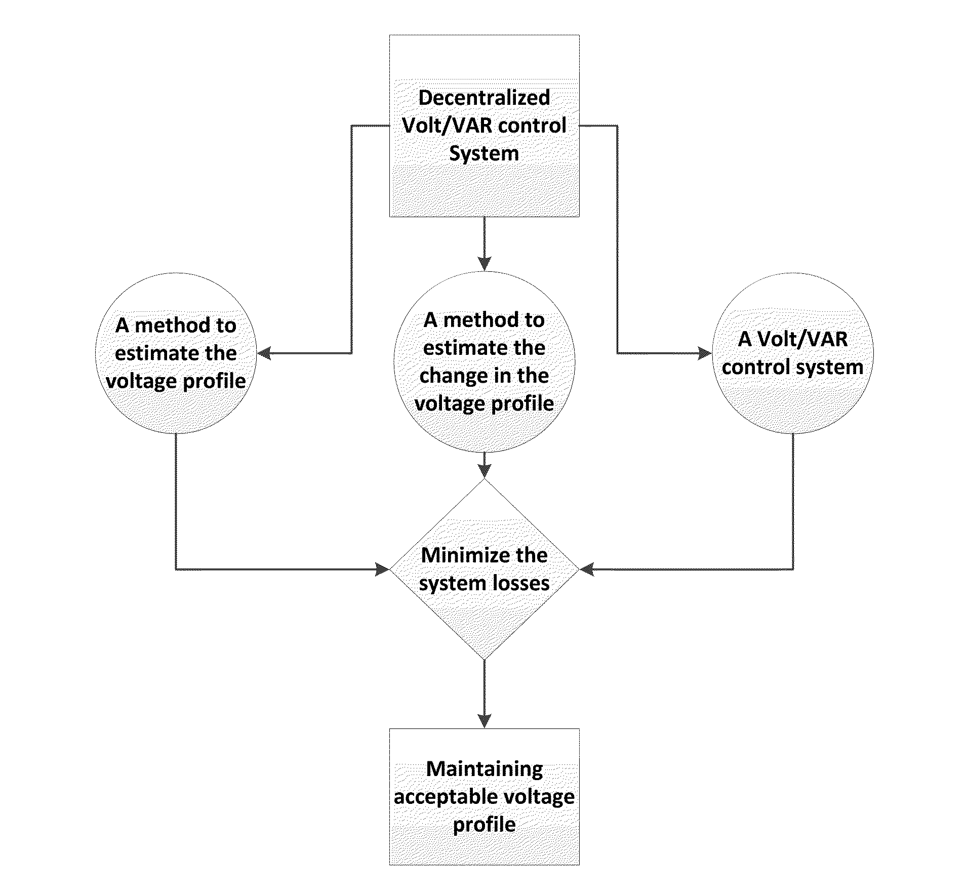
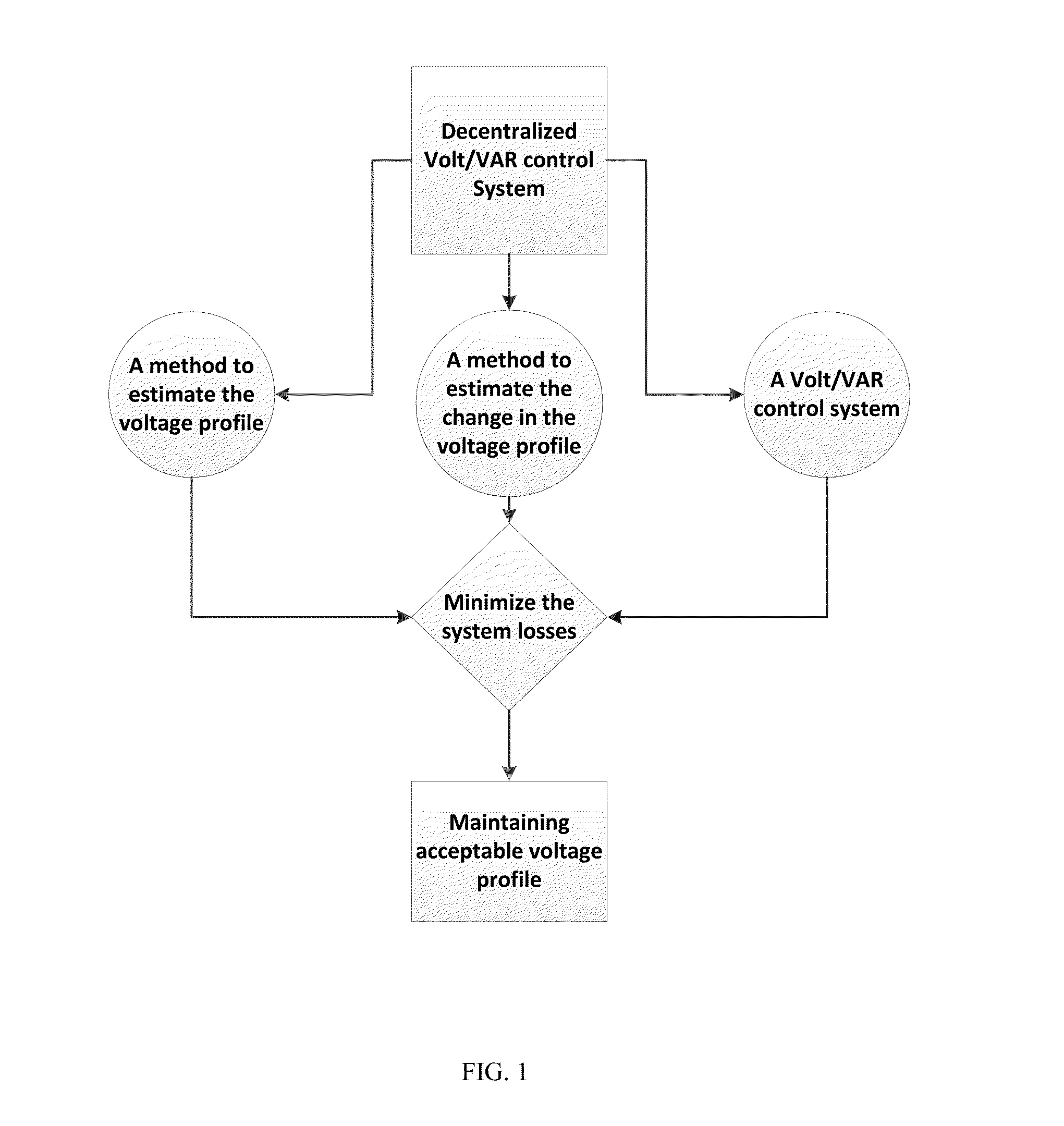
Decentralized Volt/VAR Control for Advanced Distribution Automation Systems
a technology of automation system and volt/var control, which is applied in the direction of position/direction control, instruments, electrical equipment, etc., can solve the problems of increasing the difficulty of reactive power control equipment operation, affecting posing new challenges to the operation of the distribution system, so as to achieve efficient voltage regulation and increase the penetration of dg
- Summary
- Abstract
- Description
- Claims
- Application Information
AI Technical Summary
Benefits of technology
Problems solved by technology
Method used
Image

Examples
case 2
[0119]In this case we will test the performance of the proposed technique in reaction to a change in DG output power. For the sake of simulation, assume that DG1 injects 200 kW and DG2 injects 300 kW. Based on the new power injections and after running the proposed algorithms, the capacitor RTU will get the data as provided in Table 4 for each possible reactive power injection.
TABLE 4Q = 0Q = 20Q = 40Q = 65Feeder Max Voltage (p.u)1.051.05231.05591.0603Feeder Min Voltage (p.u)1.04131.04171.04521.0425Losses index0.3700.3560.03530.0350
[0120]Although, Q=65 causes less losses, the corresponding voltage profile will not be acceptable, as it violate the 1.06 p.u. voltage rise limit. It is apparent that the optimal setting is Q=40 kVAR. To validate this results a power flow algorithm was used to calculate the losses corresponding to each reactive power injection, the results are tabulated in table 5.
TABLE 5Q = 0Q = 20Q = 40Q = 65Losses (kW)14.312.911.710.4
case 3
[0121]FIG. 12 shows the system under study of case 3. Loads and generation values are given in Table 6. For all of the following cases we assume the following data: The station bus voltage=1.055 pu, the maximum allowable voltage=1.06 pu, the minimum allowable voltage=0.94 pu, and the impedance of any line section=0.5+j0.46.
TABLE 6Bus #P(kW)Q(kVAR)2266034030455555200660157−400084545935010350114030123015
[0122]After running the algorithm described in section V, regulator's RTU will get the data in Table 7 corresponding to each possible reactive power injection.
[0123]Based on these data, the optimal reactive power is Q1=0 and Q2=40. It should be noted that, based on the actual losses obtained from a standard power flow program, the losses corresponding to the case of Q1=35 kVAR and Q2=40 kVAR is the global minimum case. The algorithm could not get this point as it had to estimate the minimum voltage points of the voltage profile, thus, the calculation of the losses index is approximate....
PUM
 Abstract
Description
Claims
Application Information