

Additive dispersing filter and method
a filter and additive technology, applied in the direction of dissolving, lubricant mounting/connection, separation processes, etc., can solve the problems of increased engine wear, depletion, contamination formation, etc., and achieve the effect of reducing the profits of the owner and increasing the downtime and operating costs of the truck
- Summary
- Abstract
- Description
- Claims
- Application Information
AI Technical Summary
Benefits of technology
Problems solved by technology
Method used
Image

Examples
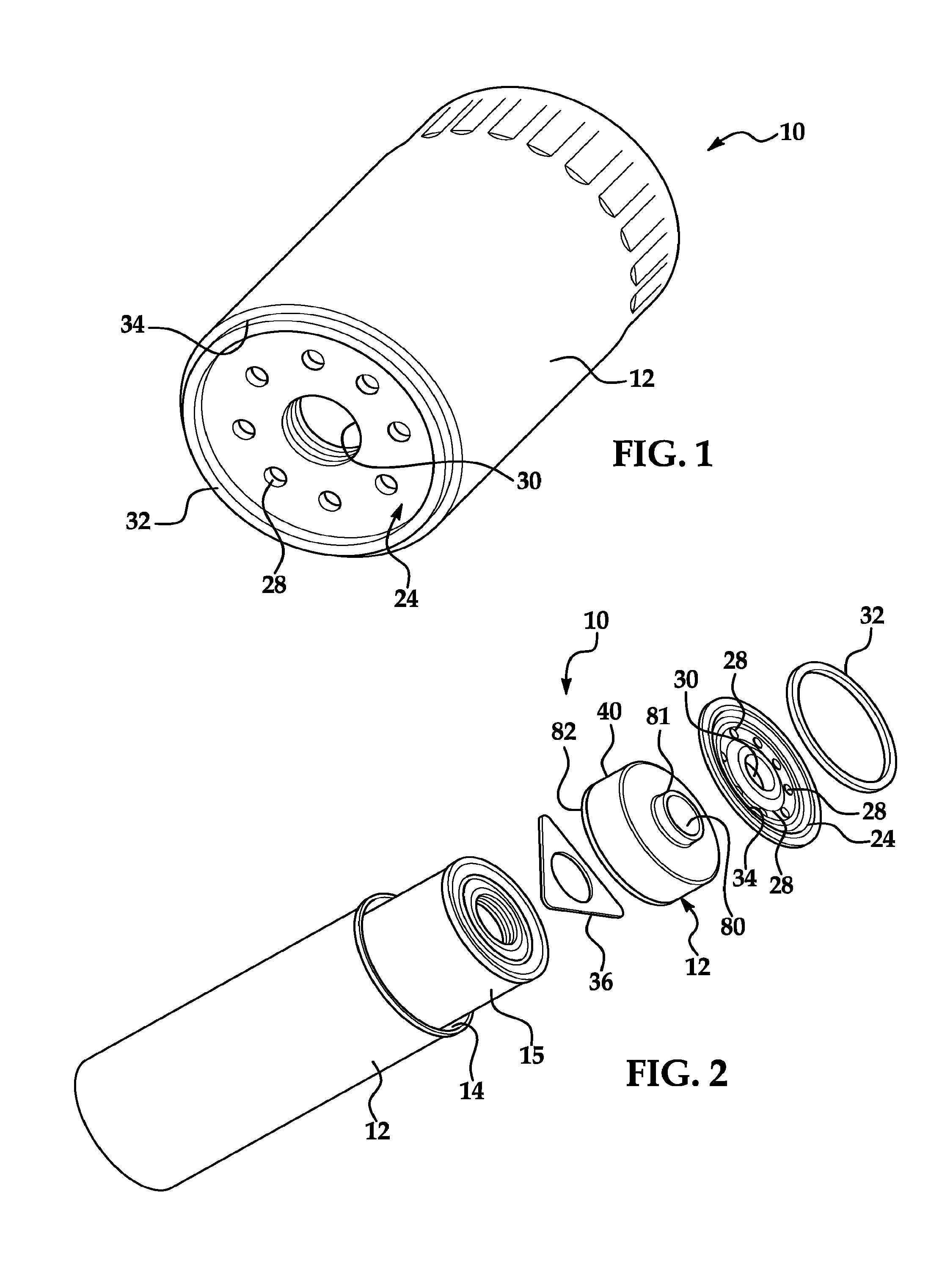
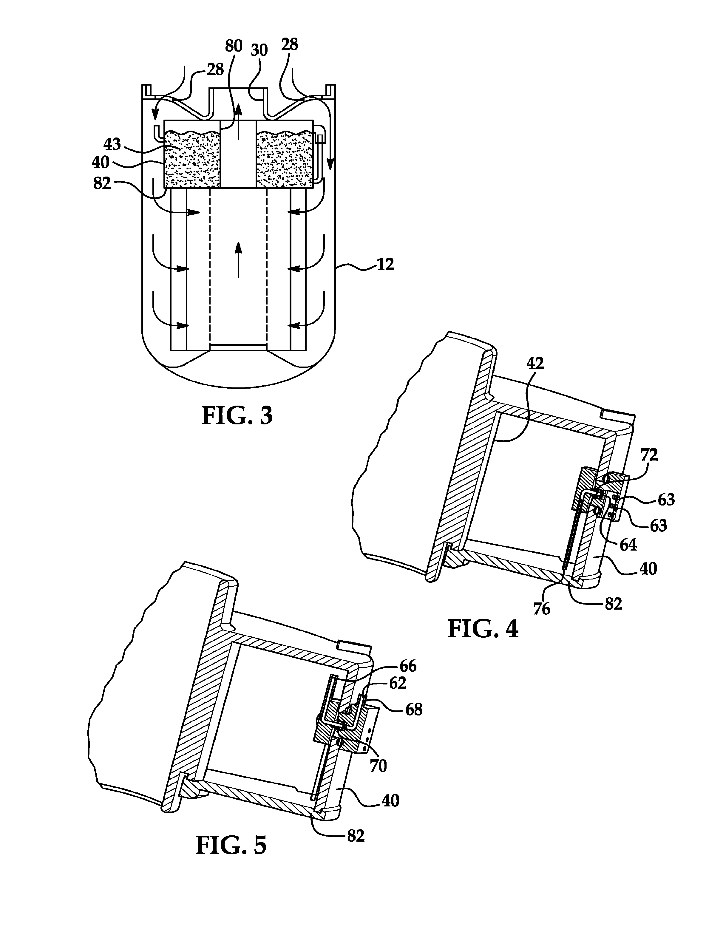
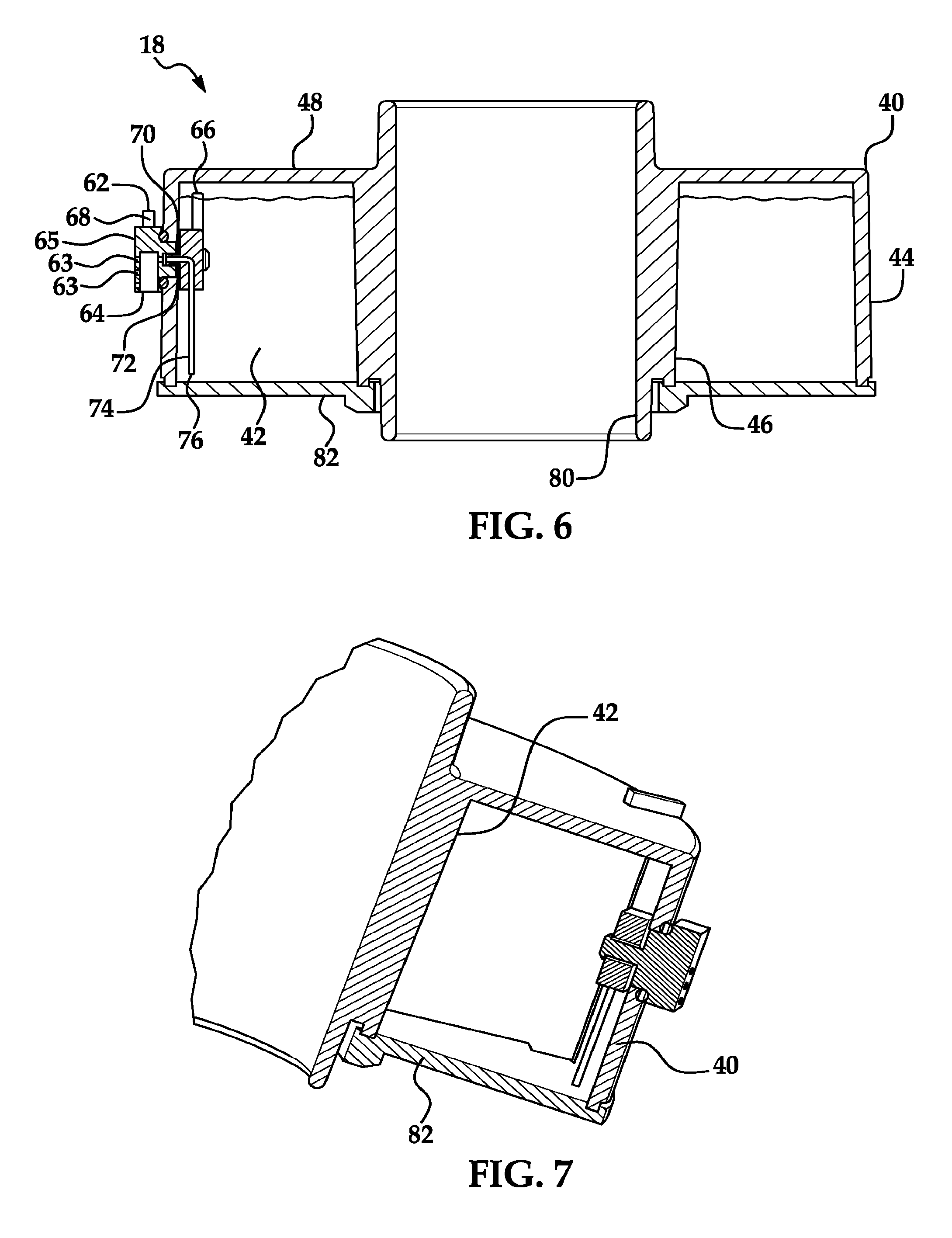
example filter
[0057 Design
[0058]Average flow rate through single filter at average speed of 60 mph-13.25 gpm.
[0059]Calculated average fluid velocity flowing past stagnation tube—2.22 ft / sec.
[0060]The fluid velocity can be calculated by knowing the area between the additive cartridge housing and the inner surface of the filter housing it is secured in, the flow rate of the fluid or oil passing through the filter can then be used to calculate the velocity of the fluid using known principles or formulas to calculate the velocity of the fluid passing through the filter.
[0061]A non-limiting example is produced below:
Stagnation Pressure CalculationsPressure = ½ *mass density* V{circumflex over ( )}2weight density of oil (lbs. / cu. Ft)56.02Mass density of oil—weight density / g 1.739751553(lb sec{circumflex over ( )}2 / ft{circumflex over ( )}4)specific gravity of oil0.898Pressure (lbs / ft{circumflex over ( )}2)4.274813125Stagnation Pressure (lbs / in{circumflex over ( )}2)0.0296862021.44inch / H2O
[0062]In one ex...
PUM
| Property | Measurement | Unit |
|---|---|---|
| inner diameter | aaaaa | aaaaa |
| diameter | aaaaa | aaaaa |
| diameter | aaaaa | aaaaa |
Abstract
Description
Claims
Application Information